
Defining Global Mesh Settings
For Icepak models, a region is automatically created surrounding the various components of the model. This is the global computational region. You are able to define mesh settings for the global region to determine mesh size and other advanced settings.
|
Name |
The Name for global mesh settings is Global by default and is not editable. |
| Enabled | The global mesh region is enabled by default and cannot be disabled. |
| Part by part meshing (Beta) | When enabled, Part by part meshing meshes each part in the model individually. See Part By Part Meshing for more information. |
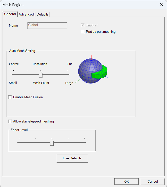
| Auto Mesh Setting | |
|---|---|
| Auto Mesh Setting | The Auto Mesh Setting slider includes a visual representation of the resolution you choose as ranging from coarse resolution with a small mesh size through a five-position scale to a fine resolution with a large mesh size. Each slider position automatically sets unique values for the following settings found on the Advanced tab: Maximum Element Size, Min. elements in gap, Min. elements on edge, Max size ratio, Multi level meshing Max. Levels, and 3D Multi level mesh. Slider settings 3, 4, and 5 also enable per-object mesh levels. |
| Enable Mesh Fusion | Enable Mesh Fusion is used to automatically group and mesh geometries in a mesh region that uses the mesh slider bar. When enabled, it divides the geometries into sub-domains, which are then meshed separately using automatically selected meshing methods to yield high quality meshes. |
| Note: Mesh fusion can be enabled or disabled on a design level in the Global Mesh Region dialog box. It can be enabled or disabled for individual mesh regions on the General tab of the Mesh Region dialog box. See Mesh Fusion for more information. | |
| Allow stair-stepped meshing | Allow stair-stepped meshing disables projection and decomposition during 3D cut cell meshing. The boundary mesh will not be conformal, and the resulting mesh will only approximate the shapes of your geometries. When enabled, stair-stepped meshing is applied to the global mesh region and all mesh regions within it. Stair-stepped meshing is not applied when User specified is enabled on the Advanced tab. Stair-stepped meshing should only be used if resolving the shape of the geometry is not important. |
| Facet Level | The Facet Level slider has a five-position scale to define the facet level of CAD objects in the design. Facet count increases as the slider position increases from 1 to 5. That is, slider setting 1 results in the fewest facets, and setting 5 results in the most facets. As the slider setting increases, the meshing of rounded corners and edges increases in resolution. |
| Maximum Element Size | |
|---|---|
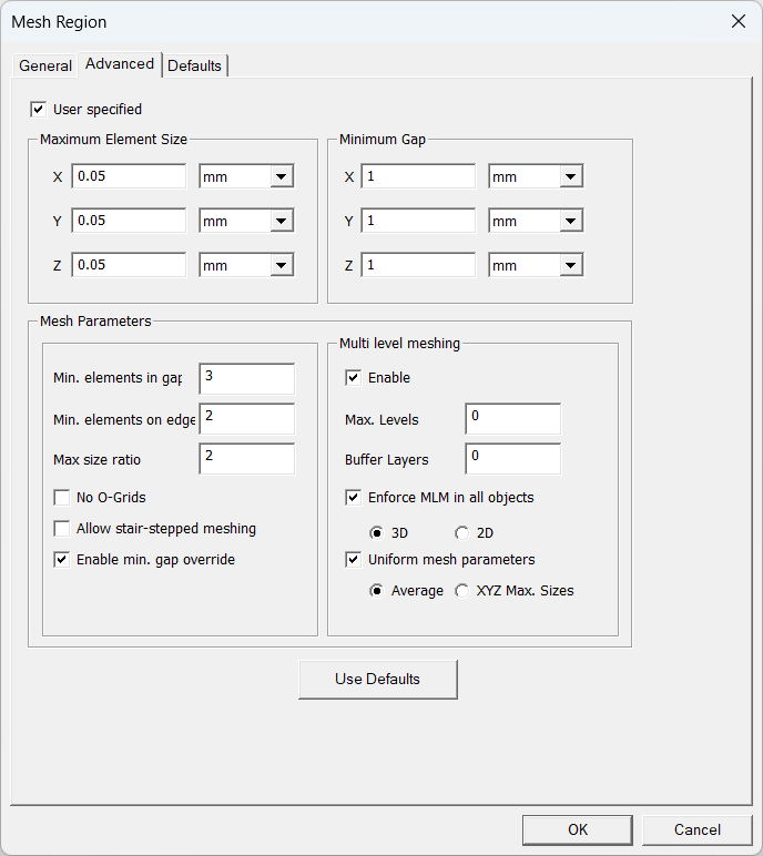
| X, Y, Z | Maximum Element Size specifies the desired maximum element length in each coordinate direction. Typical values are about 1/20 of the region dimensions in the corresponding directions. |
| Minimum Gap | |
| X, Y, Z |
Minimum Gap specifies the minimum distances separating objects in your model in the X, Y, and Z coordinate directions. Minimum gap influences geometry and meshing.
|
| Mesh Parameters | |
| Min. elements in gap | Min. elements in gap specifies the minimum number of elements between adjacent objects. |
| Min. elements on edge | Min. elements on edge specifies the minimum number of elements on each edge of each object. |
| Max size ratio | Max size ratio specifies the maximum ratio of the sizes of adjacent elements (for the whole model). |
| No O-Grids | No O-Grids (Mesher-HD and Hexa Unstructured only) specifies whether or not objects will have O-grids around them. This option is disabled by default, indicating that Icepak will generate O-grids around all objects, including those that contain other objects. |
| Allow stair-stepped meshing | Allow stair-stepped meshing disables projection and decomposition during 3D cut cell meshing. The boundary mesh will not be conformal, and the resulting mesh will only approximate the shapes of your geometries. Stair-stepped meshing should only be used if resolving the shape of the geometry is not important. |
| Enable min. gap override | Icepak computes the minimum size of bounding boxes of all objects in each coordinate direction. If this computed value is smaller than the specified Minimum Gap value, Icepak uses the smaller value when Enable min. gap override is enabled. |
| Multi level Meshing (MLM) | |
| Max. Levels | Max levels specifies the maximum number of levels that may be required to achieve the desired mesh refinement based upon curvature/proximity. For a given coarse mesh, the desired proximity/curvature based refinement may be achieved even before reaching the max levels. |
| Buffer Layers | Buffer Layers is used in conjunction with multi-level meshing. The default value is zero, which means refinement is not propagated to adjacent layers. When you set this value to a number greater than zero, such as 1 or 2, refinement is propagated to additional mesh layers, which helps in generating better meshes in the region of under-resolved geometry. |
| Enforce MLM in all objects | Enforce MLM in all objects starts with a coarse background mesh and then refines the mesh in the planar directions to resolve fine-level features. You can select to enforce multi-level meshing in 3D or 2D objects. |
| Uniform mesh parameters | Uniform mesh parameters has two options: Average and XYZ Max. Sizes. Average creates a uniform mesh with the same mesh size in all coordinate directions. The mesh size is computed by averaging the specified max element sizes.XYZ Max. Sizes creates a uniform mesh in each coordinate direction using the corresponding max element size. The resulting mesh has constant spacing in each coordinate direction but the spacing can be different if the max element sizes are different. Using uniform mesh parameters results in lower mesh count and improved quality. It is recommended to use uniform meshing parameters when multi-level meshing is used. If this option is enabled, 3D cut cells and stair-step meshing ignores the object-based parameters to keep the mesh uniform and generates better quality meshes. |
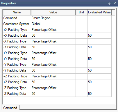
You can adjust the global region padding by selecting the region in the history tree and editing the +/-X, Y, and Z Padding Data in the Properties window. Click the Value field for +/-X, Y, and Z Padding Data to select from the following padding methods:
- Percent Offset
- Transverse Percentage Offset
- Absolute Offset
- Absolute Position
For Absolute Offset and Absolute Position, ensure the Unit is set to the appropriate unit of measure.
To define global mesh settings:
- From the Icepak>Mesh menu, select Edit Global Region.Note:
Alternatively, access the Mesh dialog box by right-clicking Mesh in the Project Manager and selecting Edit Global Region.
- If the simulation is conduction-only, select Part by part meshing to mesh parts individually. Part by part meshing is a beta option.
- In the Mesh Region dialog box on the General tab, use the Auto Mesh Setting slider to select a mesh resolution between Coarse and Fine.
- If needed, select Enable Mesh Fusion.
- If needed, select Allow stair-stepped meshing.
- Use the Facet Level slider to define the facet level of CAD objects.Note:
Facet Level settings are not applied to CAD objects imported from .stl or .tzr files.
- On the Advanced tab, if needed, select the User specified check box to enable and define the following settings:
- Maximum Element Size
- Minimum Gap
- Mesh Parameters
- Min. elements in gap
- Min. elements on edge
- Max Size Ratio
- No O-Grids
- If needed, select Enable under Multi level meshing and define the following settings:
- Max levels
- Buffer Layers
- Enforce MLM in all objects
- Uniform mesh parameters
- If needed, select the mesh region in the history tree and edit the padding values in the Properties window.
- Click OK.

|
Click here for scripting information related to this feature. |