
An IBIS buffer imported as a single component has a rectangular schematic symbol with terminals for the imported pins in the IBIS model. When individual pins have been selected, only those pins are imported. When the IBIS component definition includes a [Package Model], and Use Package Model is selected, Nexxim uses the information in the [Package Model] to instantiate RLC parasitics between the die-side and the board-side nodes. The power and ground pins become available for import, and the Component External Power property is present. Then you can connect the pins to the individual signals, power sources, and grounds in the schematic. The Component External Power property is set to ON, so the component expects power to be supplied through the component terminals. When the component definition includes a [Pin Mapping], Nexxim constructs the power and ground buses internal to the component.
The pins selected for import must include a subset of POWER and GND pins sufficient to power any power rail (bus) used by any of the imported signal pins (e.g., if one of the imported signal pins specifies a bus "VCC" in the pu_ref column of its [Pin Mapping] entry, and no power pin attached to the "VCC" bus is imported, Nexxim issues an error).
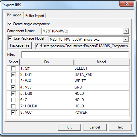
When you have identified the IBIS library file in the Import Components window, the Import IBIS window appears.
To import a single IBIS component that includes a [Package Model] with selected component signal, power, ground, and no-connect (NC) pins:
- Click the Create single component check box at the top of the Pin Import tab.
- From the Component Name field, use the drop-down menu to select the component with a [Package Model] on the IBIS file.
- If the component definition includes a [Package Model], click the Use Package Model check box and choose the package model on the drop-down menu.
- If the [Package Model] is defined in a separate .pkg file rather than in the IBIS file, click Package File and select the package model file.
- Select the chosen individual pins. Nexxim imports only the selected signal, POWER, GND, and NC pins.
- Click OK to create the component and add it to the Definitions > Components listing in the Project Tree.
(See Power Nodes in the IBIS File Import Technical Notes for details on the methods for supplying power to imported IBIS components. See Package RLC Parasitics in the technical notes for details on support for RLC parasitics in IBIS components. The next step is to place the IBIS components in the schematic.