
An IBIS buffer imported as a single component has a rectangular schematic symbol with terminals for the imported pins in the IBIS model. When no individual pins are selected, Nexxim imports all eligible pins. When the IBIS component definition includes a [Package Model], and Use Package Model is selected, Nexxim uses the information in the [Package Model] to instantiate RLC parasitics between the die-side and the board-side nodes. The power and ground pins become available for import, and the Component External Power property is present. Then you can connect the pins to signals, power sources, and grounds in the schematic. The Component External Power property is set to ON, so the component expects power to be supplied through the component terminals.
When the component definition includes a [Pin Mapping], Nexxim constructs the specified power and ground buses internal to the component. A [Pin Mapping] is required in all cases where the component has multiple POWER and GND buses. However, Nexxim can make the power bus connections without a [Pin Mapping] when there is exactly one POWER bus and one GND bus, identified by their IBIS signal_name entries. Each bus (signal_name) can have multiple pins, which are tied together. Nexxim halts with an error message if there is no [Pin Mapping] and the component does not have exactly one POWER bus and one GND bus.
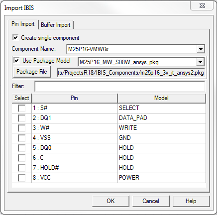
When you have identified the IBIS library file in the Import Components window, the Import IBIS window appears.
To import a single IBIS component that includes a [Package Model] and importing all component signal, power, ground, and no-connect (NC) pins:
- Click the Create single component check box at the top of the Pin Import tab.
- From the Component Name field, use the drop-down menu to select the component with a [Package Model] on the IBIS file.
- If the component definition includes a [Package Model], click the Use Package Model check box and choose the package model on the drop-down menu.
- If the [Package Model] is defined in a separate .pkg file rather than in the IBIS file, click Package File and select the package model file.
- Do not select any individual pins. With no individual pins selected, Nexxim imports ALL the signal, POWER, GND, and NC pins on the component definition.
- Click OK to create the component and add it to the Definitions > Components listing in the Project Tree.
(See Power Nodes in the IBIS File Import Technical Notes for details on the methods for supplying power to imported IBIS components. See Package RLC Parasitics in the technical notes for details on support for RLC parasitics in IBIS components.
The next step is to place the IBIS components in the schematic.