
Export Command
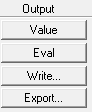
To output a field quantity or calculation result for use by some third-party post-processors, use the Export button in the calculator Output column. You can map the field quantity to either a customized grid of points specified by a points file or a three-dimensional Cartesian, Cyclindrical, or Spherical grid specified interactively through a dialog box. In the latter case, you must specify the dimensions and spacing of the grid in the coordinate system with units. For Cyclindrical and Spherical coordinate systems, you can also specify an offset from the origin.
The Export command opens the Export Solution dialog box, from which you can export the field quantity in the top register to a file, mapping it to a grid of points.
Use this command to save field quantities in a format that can be read by other modeling or post-processing software packages. Two options are available for defining the grid points on which to export:
|
Input grid points from file |
Maps the field quantity to a customized grid of points. Before using this command, you must create a file containing the points and units. |
|
Calculate grid points |
Maps the field quantity to a three-dimensional cartesian grid. You specify the dimensions and spacing of the grid in the cartesian, cylindrical, or spherical coordinates, with units that you specify. The initial units are taken from the model. |
Use of the Global Coordinate System is assumed. Local coordinate systems are not used.
To export a field quantity to a customized grid:
- Load the quantity into the top register for the fields calculator, and perform any operations on it.
- If desired, load a volume using the Geometry command.
You can use the Domain command to limit the calculation to the volume you specify. If you export a Domain filtered numeric, points that are filtered out by the domain will not be written out.
- Click the Export button in the Fields Calculator.
This opens the Export Solution dialog box.
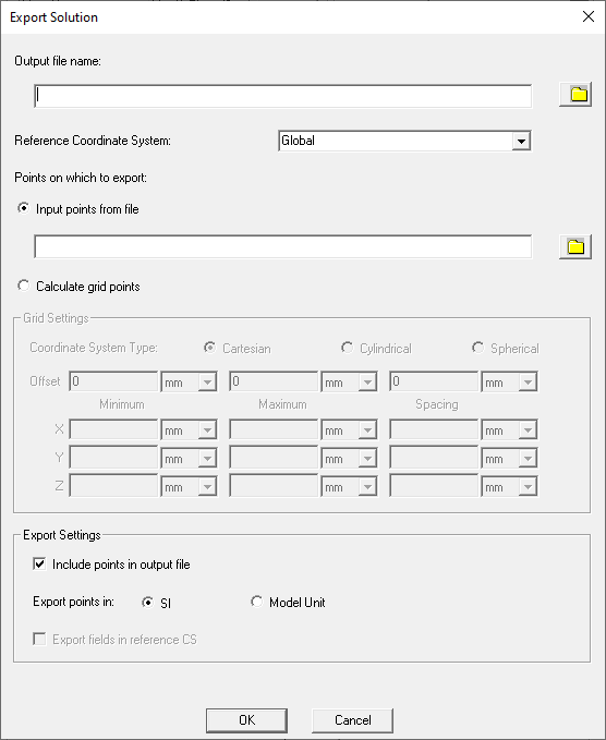
- Type or select the name of the file in which the field quantity is to be saved in the Output File Name text box. You can use the file icon to open the file browser to specify the file name and directory path. The .fld extension is automatically assigned to this file.
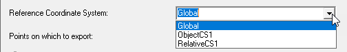
- If the design contains multiple coordinate systems, a drop-down menu lets you select the coordinate system to use. This can be helpful in evaluating the fields output when relative coordinate systems used and unitized in the design.
- Click either the Input grid points from file radio button if you have a created a .pts
file containing the grid points, or click the Calculate grid points radio button.
- If you select Input
grid points from file, either type the name and directory
of the file containing the points on which the field is to be mapped,
or, click on the file icon and use the file browser to locate the point
file (.pts extension).
Note:
The .pts file should contain the units to use for the export as shown in this file stub:
Unit=mm
-5.5 -5.5 -5.21475
-5.5 -5.5 -5.14425
-5.5 -5.5 -5.07375
-5.5 -5.5 -5.021
- If you select Calculate grid points button,
you can specify the coordinate
system as Cartesian, Cylindrical, or Spherical.
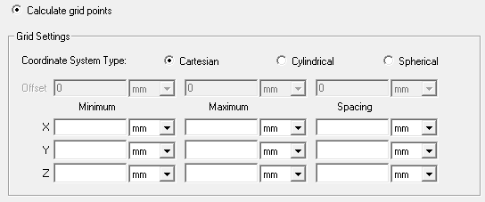
Cartesian: for each grid dimension on X, Y, and Z, enter the Minimum, Maximum, and grid point spacing.
Cylindrical: for each dimension Rho, Phi, and Z, enter the Minimum, Maximum, and grid point Spacing. You can also specify an origin of Offset.
Spherical: for each dimension R, Theta, and Phi, enter the Minimum, Maximum, and grid point Spacing. You can also specify an origin of Offset.
Note:When you export fields on a 1D or 2D line/surface from the field calculator, the start and stop values must be the same for one or two of the coordinate system start/stop ranges. If you specify a zero spacing for a dimension, the export uses only the minimum value.
The default coordinate system will be Cartesian. The default offset will be all zeroes. The length units will default to model unit and default angle unit will be degree. At the start the minimum/maximum/Spacing entries are blank. The user entered values are not remembered when the dialog is closed.
- If you select Input
grid points from file, either type the name and directory
of the file containing the points on which the field is to be mapped,
or, click on the file icon and use the file browser to locate the point
file (.pts extension).
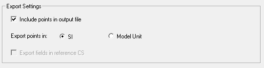
- For larger files, for the Export Settings,you may want to uncheck the Include points in output file box. If you uncheck the box, the file header will include minimum, maximum and spacing information from which you can recalculate the grid points.
- You can also specify SI or Model Units. Modul Units can be helpful to evaluate the fields output when relative coordinate systems are unitized in the design.
-
If field to be exported has type vector or complex vector, the 'Export Field in reference CS' checkbox is enabled and you can specify that field to be exported in reference CS. It can be helpful to evaluate the fields output when rotated coordinate systems are unitized in the design
- Click OK to export the file.
The field quantity is mapped to the grid and saved to the file you specified (.fld extension.).