Creating Radiation Patterns
A radiation pattern is a 2D polar plot displaying the intensity of near- or far-field radiation patterns. It is divided by the spherical coordinates R and theta, where R is the radius, or distance from the origin, and theta is the angle from the x-axis. Following is the general procedure for drawing a radiation pattern of results:
- Click HFSS>Results>Create Far Fields Report>Radiation Pattern, or right-click the Results icon in the Project tree and click Create Far Fields Report>Radiation Pattern.
The Report dialog box appears, and a
Radiation Pattern Plots icon appears under Results in the Project tree.
- In the Context section make selections from the following field or fields, depending on the design and solution type.
- Solution field with a drop down selection list. This lists the available solutions, whether sweeps or adaptive passes.
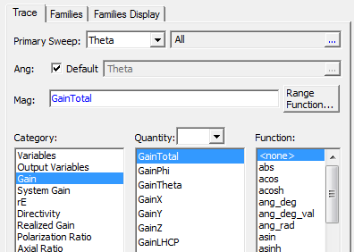
- In the Trace tab area, specify the Primary Sweep and Ang information to plot along the R-axis, or the axis measuring magnitude. The Primary Sweep field has a drop-down menu of current choices for Theta, Phi, and defined variables. Click the ellipsis button if you want to select from available values.
- In the Ang, if you want to change the default, uncheck to enable the field and ellipsis button.

- On the Category drop-down menu, click the type of information to plot. The selected category also provides the default plot name.
- On the Quantity list, click the values to plot. Use Ctrl+click to make multiple selections.
- In the Function list, click the mathematical function to apply to the quantity for the plot.
- The Mag field displays the currently
specified Quantity and Function. You can edit this field directly.
Note:
Color shows valid expression.
- Range Function button -- opens the Set Range Function dialog box. This applies currently specified Quantity and Function.
- The Families tab is helpful if you want to use the plot as an overlay and you need to restrict the Phi (default) or Theta values to make the plot appropriate for overlay. See Overlaying 2D Radiation Field Plots on Models.
- Click New Report.
This creates a new report in Project tree, displays the report with the defined trace, and enables Add Trace on the Report dialog box. The default name is based on the Report Category you selected, for example, System Gain Plot n or Directivity Plot n. You can edit the plot names in the project tree and the plot header text in the report synchronizes.
The function of the selected quantity or quantities will be plotted against the values you specified on a 2D polar plot. The plot is listed under Results in the project tree and the traces are listed under the plot. When you select the traces or plots, their properties are displayed in the Properties window. These properties can be edited directly to modify the plot.
- Optionally, add another trace to the plot by following the procedure above, using Add Trace rather than New Report.
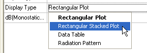
You can also modify the display type of an existing plot from the Properties dialog for that plot. Select the Report icon in the Project tree to display the Properties dialog box. Selecting the Display Type field displays a menu with selections available for that plot.

Once you make a selection, the plot display updates for the current selection.
