Project Sheet Object
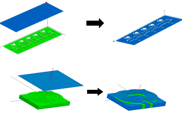
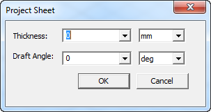
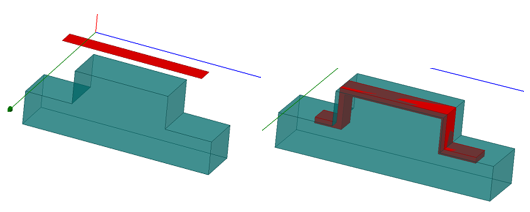
Use the Modeler> Surface> Project Sheet command to apply a selected planar sheet object to a suitable 3D object. This permits easy modeling of thin conformal deposits. (The Wrap Sheet and Imprint Projection commands are not suitable for this use.) For modeling conformal deposits when using Project Sheet, you can specify a thickness and a draft angle.
To use the Project Sheet command you must select one planar sheet and at least one solid body. If you select multiple solids, the sheet is project on all bodies as if they have been united. After the commend executes, a new sheet that lies on the surface of the selected bodies is created. The solid bodies are not changed.
Faces that are hidden from the sheet being projected are not covered, due to the projected sheet.
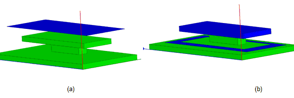
Only vertical faces (or faces parallel to the projection direction) that lie completely within the projection of the sheet will be covered by the projected sheet. Vertical faces that lie on the boundary of the projection are not covered.
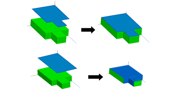
If the sheet cross-section exactly matches the body cross-section, no vertical faces are covered. If the projected sheet exceeds the cross-section of solids, faces that lie with in the sheet projection are covered.
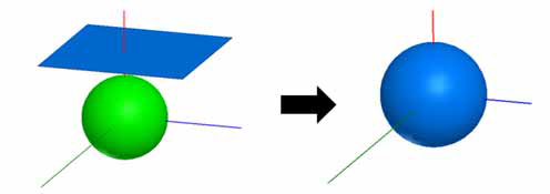
If a surface like a cylinder or sphere lies completely within the sheet projection, the entire surface will be covered, though there may be a warning that “Output may be incorrect because a self-obstructing face was found.”
To Project a Sheet:
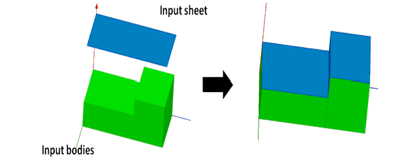
- Select a planar sheet object and one or more appropriate solid objects.
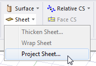
- From the menu bar, click Modeler> Surface> Project Sheet or, on the Draw ribbon tab, click Sheet> Project Steet:
For modeling conformal deposits, you can also specify a thickness and optional draft angle.
After you perform Project Sheet, the History Tree shows the Project Sheet command and the create command for the imprinted object. If you select the Project Sheet command in the History Tree, you can suppress the command via the docked Propertieswindow. If you select the Create <object> icon for the object, you can edit the properties of that object. The changes applied to the object carry over to the imprinting.
Specifying a Thickness value has different effects depending on whether the value is positive or negative. The following figure shows the effect of a positive thickness, with the Projected sheet taking its thickness outward from the target object.
The following figure shows the effect of a negative value for thickness.
When a negative value is given the thickness will be limited by the target solid body. That is, the thickness can not be beyond the original solid body which was chosen. If you use a negative thickness it is also possible that not all overhangs will be eliminated.
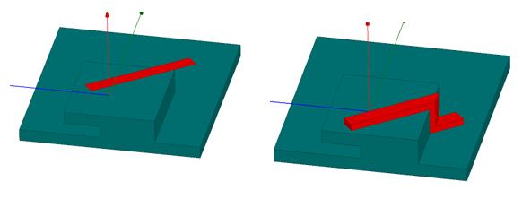
The following figure shows the effect of a 45 degree draft angle.
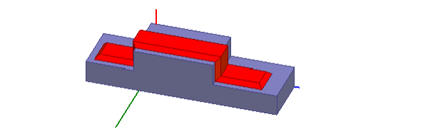
Other examples of Project Sheet on complex models are show in the following figure.