
Applying Curvilinear Elements
For HFSS, Maxwell, and Mechanical designs, Curvilinear elements provide an accurate representation of the CAD model geometry by improving the conformity of element nodes to curved CAD surfaces. You can apply curvilinear elements as a Mesh Operation on selected curved model faces see procedure below or as a global option in the Initial Mesh Settings dialog box.
For HFSS designs:
When curvilinear elements are applied globally or to specific faces, the meshing process attempts to pull all nodes associated with a curved face mesh (both corner nodes and midside nodes) to the CAD faces. Ten-node tetrahedral elements are employed, with four corner nodes and six midside nodes. Therefore, with the midside nodes pulled to curved CAD faces, the element edges can be non-straight. See Apply Curvilinear Elements Discussion.
How to Apply Curvilinear Elements to Specific Curved Faces:
- Select the object or face to which you want to apply curvilinear elements.
- Select Mesh in the Project Manager, right-click for the short cut menu and select Assign Mesh Operation > Apply Curvilinear Meshing.
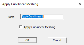
- Either accept the default name or provide one of your own.
- Select Apply Curvilinear Meshing.
- Click OK.
The Apply Curvilinear Meshing dialog box appears.
The defined Mesh Operation appears in the Project Manager.