Using Field Solutions from Other Simulations
HFSS can use dynamic links to other simulation tools to create one seamless workflow. The source designs can be created in HFSS, HFSS 3D Layout, SIwave or Maxwell3D. Some example uses for dynamic links include:
- a detailed and optimized design of a cell phone radiating in a large environment (HFSS to HFSS).
- a Driven Modal (HFSS to HFSS SBR+).
- a complicated printed circuit board in an HFSS 3D Layout project file causing EMC/EMI problems in and around its housing (SIwave to HFSS).
- an electromechanical component causing EMC/EMI problems in a vehicle (Maxwell3D to HFSS).
In all cases, radiated fields from the source project are imposed as an incident wave in the target project. These radiated fields can be far fields and near fields.
It may be necessary to create the environment variable SIWAVE_INSTALL_DIR before executing the target application (e.g., SIwave is launched from HFSS and not separately).
From the target project, radiation boundaries must be assigned to specify where the fields from the source project enter the target project.
To avoid singular far field integral calculations, do not use identically sized and shaped surfaces in the target and source projects. Use surfaces that are smaller or larger.
Using a Dynamic Link Between HFSS and HFSS 3D Layout (Example)
To execute the following instructions, the user will need an Ansys Electronics Enterprise license or an Ansys Electronics Premium SIwave Plus license.
Add a dynamic link between HFSS and HFSS 3D Layout to utilize HFSS 3D Layout's built-in SIwave Near Field solver. Among other benefits, integrating HFSS and HFSS 3D Layout allows bidirectional data and eliminates manual steps in the process, saving time and improving accuracy.
Complete the following steps to create a dynamic link between HFSS and HFSS 3D Layout.
-
From the appropriate target HFSS file, create an Incident Plane Wave excitation.
-
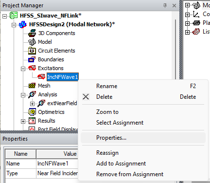
From the Project Manager window, expand the Project Tree > active design folder (e.g., HFSSDesign2) > Excitations. Then do one of the following to open the Incident Wave Source window.
-
Double-click the excitation (e.g., IncNFWave1).
-
Right-click the excitation and select Properties.
-
-
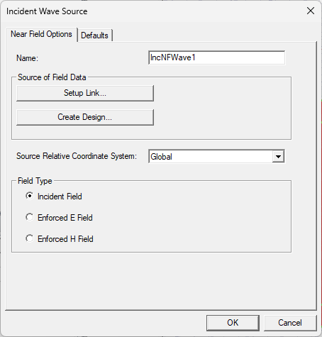
From the Incident Wave Source window, enter a Name for the excitation or accept the default (e.g., IncNFWave1).
-
From the Source of Field Data area, click Setup Link to open the Setup Link window.
-
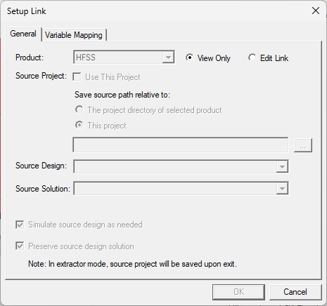
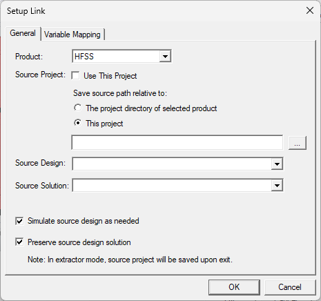
From the Setup Link window, click Edit Link to activate the window and make its contents editable.
-
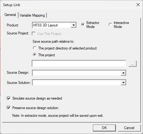
Select HFSS 3D Layout from the Product drop-down menu.
-
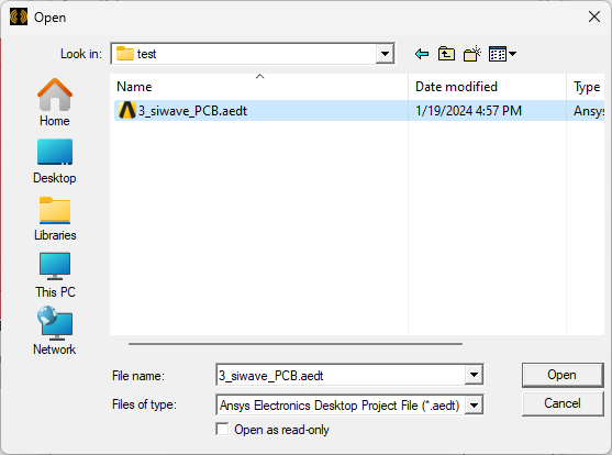
Click the ellipsis adjacent to the empty field to open an explorer window. Then navigate to the appropriate project file. Either double-click the file or select it and click Open.
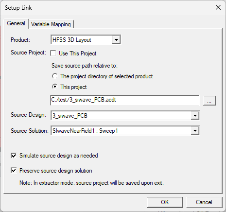
The Setup Link window will populate with the path to the source file, the available designs, and the available solutions. If the user has not already opened the source file, it will open in Electronics Desktop and appear in the Project Manager window.
-
-
If necessary, select a more appropriate Source Design and/or Source Solution from the drop-down menu(s).
- Check or uncheck the boxes adjacent to the following options:
- Simulate source design as needed — if the source design has been modified, select this option to update the source design solution linked to the target design.Note:
Ensure the cached link data in the target design is invalidated before proceeding (i.e., from the Project Manager window, right-click Analysis and select Clear Linked Data.
- Preserve source design solution
— if the source design is closed, it is not included in the Project Manager window containing the target design and the source design will not
be saved. Select this option to save the design.Note:
Preserve source design solution is most useful if the source design is an HFSS 3D Layout, Maxwell, or SIwave file.
- Simulate source design as needed — if the source design has been modified, select this option to update the source design solution linked to the target design.
-
Click OK to close the Setup Link window and establish the link.
-
Click OK to close the Incident Wave Source window.
-
From the Project Manager window, expand Analysis. Then right-click the near field solution (e.g., extNearField1) and select Analyze to begin analysis.
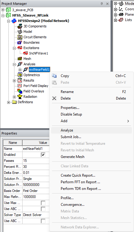
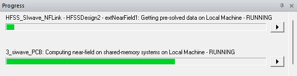
As the analysis proceeds, view its status in the Progress window.
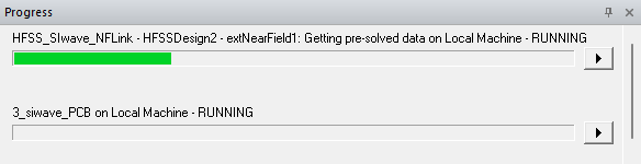
The analysis will utilize HFSS 3D Layout's SIwave Near Field solver to complete the simulation.