Mesh Fusion
With mesh fusion you can specify that multiple design modal FEM components and native regions are meshed independently to ensure very robust and rapid meshing. If a design contains multiple instances of a component, that component need only be meshed once. Parametric variations for one or more instances only affects the mesh of those instances. You can access the Do Mesh Fusion dialog through the Project tree shortcut menu for 3D Components, using the Set Components for Mesh Fusion... command. You can use the dialog to manage settings for all components in the project.
The solver supports mesh fusion for FEM volume and HFSS 3D Layout components in HFSS design type. This type of volume component cannot coexist with any FEBI, and/or surface and/or SBR+ components. Similar to 3D components, HFSS 3D layout components, when marked as mesh fusion, also support mesh envelope padding and mesh setting override. The mesh setting override dialog for layout components are different from that for 3D components and can be seen in the figure below.
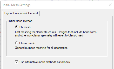
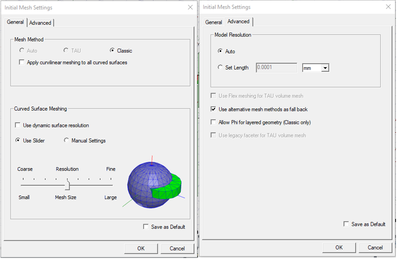
In this dialog, you can choose different mesh methods specific to layout components. This dialog is fully modeless, which loads different pages when you select layout or 3D components. In addition to this dialog, the Initial Mesh Setting dialog for the native design is also modified. If there are layout components meshed in native, the Initial Mesh Setting dialog will disable the Auto and TAU mesh method. The options related to TAU in the advanced setting page are also disabled.
With the proper setting, the design can be meshed and solved. Layout components marked as mesh fusion will have full interaction with other layout components, 3D components and native geometry.
Some of the benefits of Mesh Fusion are as follows:
- Systems with large variation in length scales can be successfully meshed. For example, in the case of a small 3D antenna touching an aircraft, you can mesh both the bodies separately and ensure a conformal mesh between them. That is, the triangulations in the contact area between the volume mesh of the 3D antenna component and the surface mesh of the aircraft are aligned resulting in a conformal mesh.
- You can select different meshers for each component via the Component Meshing properties, or directly . That is, you can pick the Tau mesher for a given component and the Classic mesher for another component, in order to ensure system meshing is successful.
- The iterative solver option is available for mesh fusion projects as an Advanced Solution Setup option, except for 3D component array in both 3D layout and MCAD. The Iterative solver uses 1.e-6 as the default.
- Faster meshing for multiple instances of the same component is possible: only one initial mesh is created. For instance, when multiple identical antennas appear in a design, only one needs to be meshed.
- Mesh resuse enables fast placement studies. If you move a component, no re-meshing needs to be done. Also only the last adaptive mesh is used and no adaptive meshing of the component needs to done.
- Reused initial meshes are not impacted by any parametric variation. Suppose there are multiple components that are independently meshed and you make a parametric variation in one component, the remaining components are not remeshed. In this situation, the last adaptive mesh cannot be reused. Some examples of parametric variation can include increasing or decreasing the dimension of a geometry or changing the material properties.
- Mesh fusion can be distributed, including support for distributing Iterative Solver Excitations.
-
Mesh Fusion components can be marked as Priority in the Mesh Fusion Settings dialog box. It is common for a large project to have some native objects intersect with mesh fusion components due to user error or modeling issue. These intersections are usually small and would not affect simulation result if ignored, but they can stop simulations and cost much time to fix. To improve this problem, you can mark any mesh fusion components as priority.
If a priority mesh fusion component intersects a native object, the intersecting portion is subtracted from the native object, so that the simulation continues.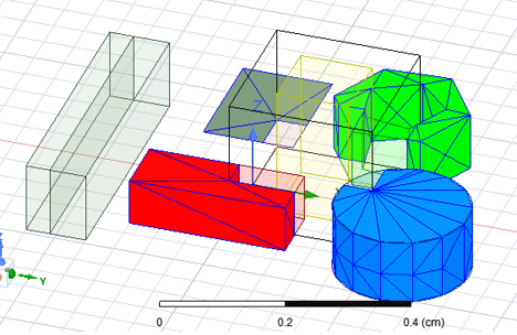
-
If the intersection portion has boundary assignment, the simulation will still report error
-
If two mesh fusion components intersect each other, the simulation will still report error
-
Any overriding mesh setting appears in each component’s property window.
-
The current release of Mesh Fusion now can share surface approximation operation between imprint face pairs that have curved outlines. Take surface approximations assigned on face, on body, and on the component level for both faces of the imprint pair and combine them to create the operation that results in finest mesh. This will only be done for face pairs that have classic mesh method on both sides. (TAU mesher does not support assigning surf approximation on planar faces, even if they have curved edges.) You can automatically assign 15 degrees normal angle to all shared mesh operations by env var ASSIGN_15_DEG_NORMAL_DEV_TO_CURVE_IMPRINT. This approach does not support array in native.
-
You can generate field plots using data from either side of the boundary surfaces, using the “Adjacent side” check box on the Field Plot dialog, despite the sides belonging to different meshes and domains.
Layout components that are marked as Mesh Fusion also support the priority option. The priority option provides a way to resolve component intersection conflicts with native objects. If such intersection appears, the intersecting portion will be subtracted from the native object, so that the components marked as priority stay intact and the simulation could continue. For example, consider a design with layout component being intersected by a native box.
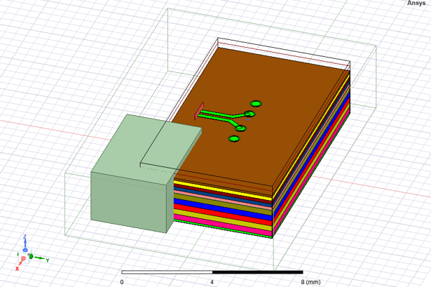
If the priority option is not marked for this layout component, the simulation reports error. If the component is marked as priority, then the intersecting portion is subtracted from the native object, and the simulation can complete. You can plot mesh on the native objects to confirm that the subtraction is applied, and the mesh for the layout component marked as priority is intact.
Some limitations of mesh regions include:
- Unless marked as Priority, Mesh region cannot intersect with each other or any non-assembly geometries.
- Mesh region cannot contain each other or any non-assembly geometries.
- Mesh region must have all planar faces.
- Any face of a mesh region cannot contact following boundaries:
- port
- boundaries with shell element enabled
- boundaries containing spatial or temperature dependent material
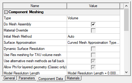
You can access the setting through Component Meshing properties.
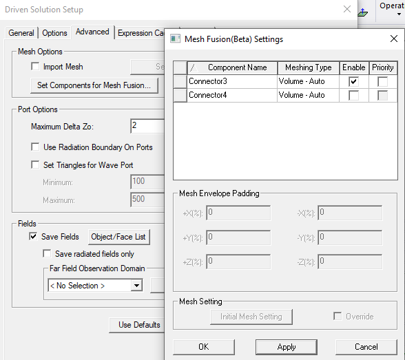
You can also access Mesh Fusion through the Advanced tab of the Solution Setup.
If a component does not meet the requirements for Mesh Fusion, the feature is disabled in the Do Mesh Fusion dialog and the Component Meshing properties.
Mesh Envelope Padding for Components without a User-defined Mesh Envelope
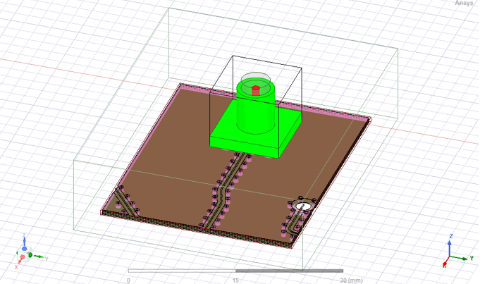
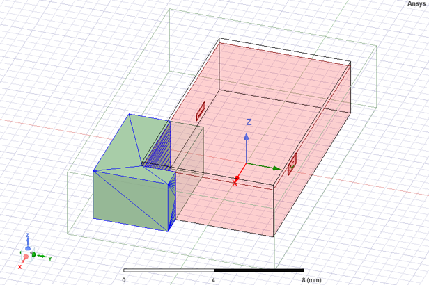
For each component used in mesh fusion, a tight bounding box is automatically created in the component’s target coordinate system. This tight region box is referred as ‘mesh envelope’. You can visualize such mesh envelope from the modeler window. See the example below.
To override this automation, users can manually assign mesh region to a single solid solve-inside model object which must contain all geometries in the design. Manual mesh region is needed in following scenarios:
- To avoid overlap with native geometry or another component
- To avoid contact with internal faces when possible. This will improve mesh quality leading to better solver performance.
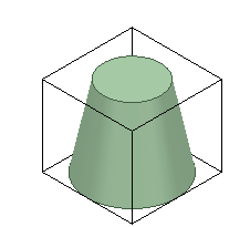
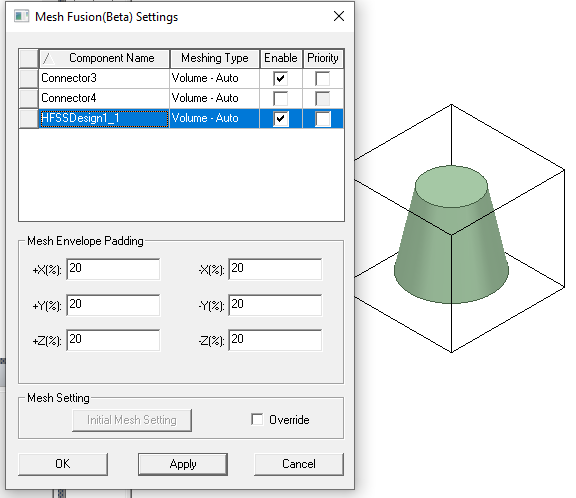
For each component without a manually assigned mesh envelope, users can add padding to its mesh envelope in all 6 directions of its target coordinate system. The example below shows the same component discussed above with 20% padding added to all directions of its mesh envelope.
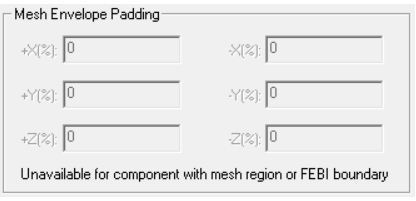
If a component has user-defined mesh envelope or is not a FEM volume component, the mesh envelop padding is disabled with a warning message.
Mesh Method Override
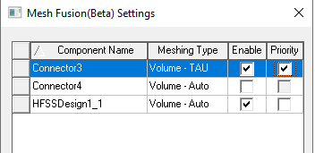
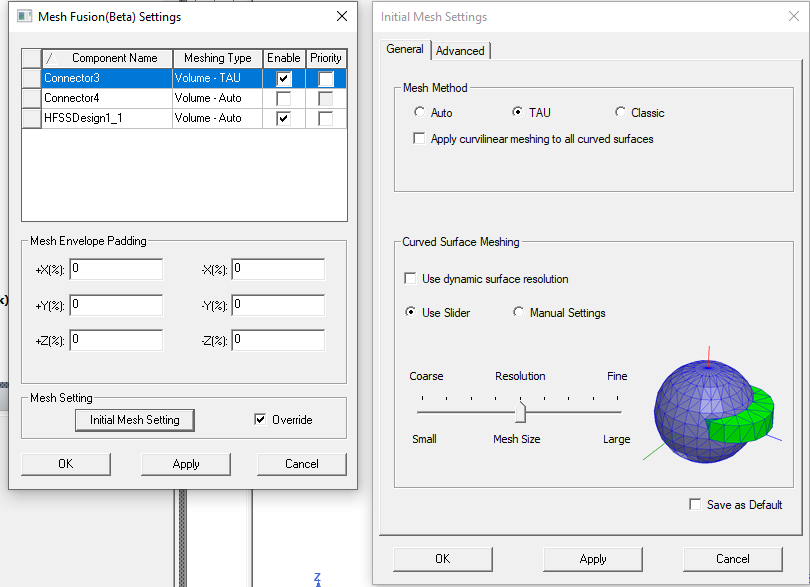
You can override the mesh method from the component definition in the Mesh Fusion Setting dialog box, accessed either through the 3D Component shortcut menu in the Project tree, or the Advanced tab of the an Advanced Solution Setup. This lets you deal with potential mesh failure based one specific mesh method when doing assembly meshing. If a failure happens using one method, you can easily switch the mesh method and try again. Selecting a component in the Mesh Fusion Setting dialog enables the region, where can check Override, and then select, Auto, TAU, or Classic. For convenience, the dialog also displays each component’s meshing method in its Meshing Type column.
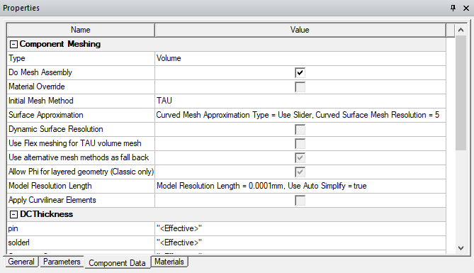
The Component Mesh settings will appear in the Component Properties window, Component Data tab.
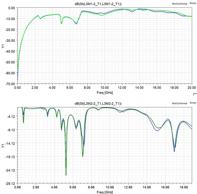
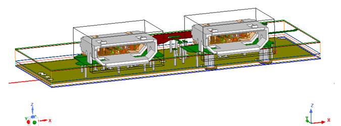
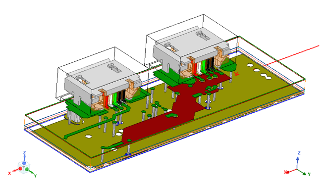
Example: USB Socket
This example shows a circuit board with two USB sockets. The USB sockets are FEM components with custom defined air box as mesh regions.
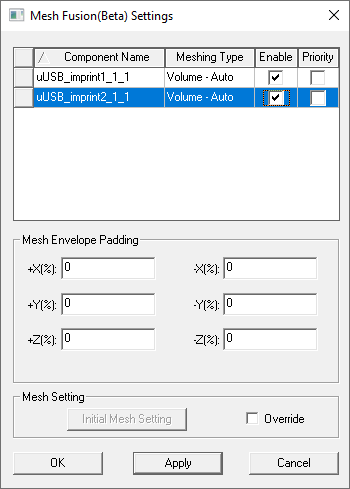
You can set the Do Mesh Fusion property of each components by accessing the Do Mesh Fusion dialog through the Project tree shortcut menu for 3D Components.
The plots below show the comparison of terminal S parameters between designs in which the components are set for mesh fusion (solid line) or not (dashed line).