Chirp Sequence FMCW for SBR+ Range Doppler Solution Setup
The Chirp-Sequence FMCW (CS-FMCW) waveform option models radar transmission of a uniform amplitude sinusoid whose frequency continuously rises from a low value to a high value that straddles the center frequency. This is known as a “chirp”. Unlike the pulse-Doppler waveform, where the transmitter issues a very short duration pulse followed by an extended quiet time while one or more receivers listen, the FMCW transmission has orders of magnitude longer duration and corresponding lower peak power, and the receivers listen while the rising-frequency chirp is being broadcast. With the CS-FMCW waveform, the range to each scattering feature is proportional to the difference in the current transmission frequency with that of the received signal component due to the scattering feature. This frequency difference is measured by mixing (multiplying) the current transmission RF signal with the received signal, low-pass filtering it, and FFTing the resulting baseband signal to produce a response vs. beat-frequency. The beat-frequency axis is then rescaled according to the frequency ramp rate and speed of light to yield the response vs. range (distance). Like the pulse-Doppler waveform, with the CS-FMCW waveform, chirps are issued and observed in a sequence over a coherent processing interval (CPI) to yield many range responses, and these are then FFT’d across the sequence to yield the response vs. range vs. Doppler velocity.
CS-FMCW is generally considered more practical to implement than the pulse-Doppler waveform owing to its significantly lower peak-power. Moreover, CS-FMCW requires no more total time (CPI duration) than a corresponding pulse-Doppler waveform to achieve a given level and resolution and ambiguity in range and velocity. Although the chirp duration is much longer than the corresponding pulse, this extended chirp duration is merely replacing the extended quiet time required by the pulse-Doppler waveform. However, FMCW waveforms do introduce an artifact known as range-velocity coupling. Because FMCW radars measure range according to the frequency difference between received signal and the current broadcast shift, and moving scatterers cause a Doppler shift in the received signal, there is a shift in the perceived range to scattering features. The range shift is proportional to the center frequency of the FMCW ramp and each scattering feature’s radial (Doppler) velocity relative to the radar, and it is inversely proportional to the FMCW frequency ramp rate (that is, the bandwidth divided by the chirp duration). The Chirp-Sequence FMCW waveform option in HFSS SBR+ incorporates this range shift into its simulations, but toggling off the Include Range-Velocity Coupling Effect will artificially suppress this effect.
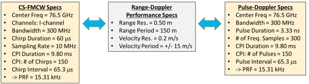
Waveform/CPI Parameters and Range-Doppler Image Properties are interchangeable.
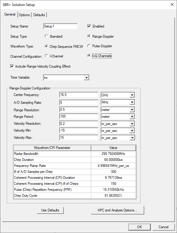
In the SBR+ Solution Setup, setting Waveform Type to Chirp Sequence FMCW (default) exposes additional options and settings relative to the Pulse-Doppler waveform option: Channel Configuration (I-Channel or I+Q Channels), A/D Sampling Rate, and whether the waveform model should Include Range-Velocity Coupling Effect. Additional rows will also appear in the non-editable Waveform/CPI Parameter table located below the waveform input settings: Chirp Duration, Frequency Ramp Rate, # of A/D Samples per Chirp (replacing # of Frequency Samples), and Chirp Duty Cycle.
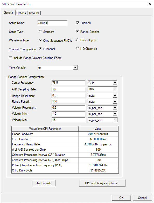
When Waveform Type is set to Chirp-Sequence FMCW, the default Channel Configuration is I-Channel, Include Range-Velocity Coupling Effect is engaged (more accurate), and the default A/D Sampling Rate is 10 MHz. In the CS-FMCW waveform model of HFSS SBR+, the latter setting controls the sampling rate of the analog-to-digital converter that samples the received signal after it has passed through the waveform model’s mixer and low-pass filter. If the Channel Configuration is set to I+Q Channels, then this controls the sampling rate for both channels in tandem. For given Range Resolution and Range Period inputs, increasing A/D Sampling Rate reduces the Chirp Duration and Chirp Duty Cycle reported in the Waveform/CPI Parameter table.
The Chirp-Sequence FMCW waveform settings will not be accepted unless the Chirp Duty Cycle is less than 100%, meaning that the Chirp Duration is less than the start-to-start interval between chirps within the CPI, the latter quantity being the reciprocal of Pulse (Chirp) Repetition Frequency (PRF); issued chirps cannot overlap. If the Chirp Duty Cycle reports as exceeding 100%, you must either reduce the Chirp Duration or expand the interval between chirps. You can reduce Chirp Duration by increasing the A/D Sampling Rate, increasing the Range Resolution, or decreasing the Range Period. You can expand the interval between chirps by reducing the difference between Velocity Max and Velocity Min.
As with the case of the Pulse-Doppler waveform, the input dialog for CS-FMCW settings will not permit the product of Range Period (ambiguity) and velocity period (Velocity Max – Velocity Min) to exceed the theoretical limit of c2/(4 fc), where c is the speed of light and fc is the center frequency.
Switching the Channel Configuration from I-Channel to I+Q Channels while holding all other input settings fixed will cause corresponding changes in the non-editable Waveform/CPI Parameter table: Chirp Duration, # of A/D Samples per Chirp, and Chirp Duty Cycle will drop by half, while Frequency Ramp Rate will double. This is because, all other system parameters remaining the same, an I+Q configuration generates twice as much information as its I-Channel counterpart, which will double the range period. But if we hold Range Period fixed while going from I-Channel to I+Q Channels, then the above mentioned quantities must change instead, and in the indicated manner. Alternatively, an equivalence in performance and system specifications between an I-Channel and an I+Q Channels configuration can be achieved by reducing the sampling rate of the I+Q channels configuration by one-half relative to its I-Channel counterpart. However, the results will not be exactly the same, and the I+Q Channels configuration will yield range-Doppler images with reduced signal-processing artifacts.