
Assigning Lumped RLC Boundaries
A lumped RLC boundary represents a parallel or serial combination of lumped resistor, inductor, and/or capacitor applied to a surface. Multiple RLC boundaries can be used to model other circuit configurations. For example, a lumped RLC serial circuit connection can be modeled with three connected RLC surfaces: one with only resistance, one with only inductance, and one with only capacitance.
To create a lumped RLC boundary:
- Select a surface
on which to assign the boundary and click HFSS >Boundaries>Assign>Lumped
RLC to bring up the Lumped RLC Boundary
dialog box.
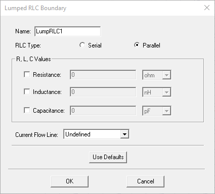
- Select Resistance, Inductance, and Capacitance as needed and specify values and units for each selected element. Optionally, you can assign a variable to any of these values.
- To specify where on the surface the current
and voltage will be controlled, define a Current
Flow Line. The selection field initially appears as Undefined. Select New
Line to define a vector
line on the boundary surface.
Note:
HFSS assumes the lumped RLC is assigned to a rectangular face. If you assign a non-rectangular face, HFSS issues a warning, but proceed with the solution. Using a non-rectangular face can result in less accurate representation of the lumped RLC. See the technical notes on RLC boundaries for more information.