
Assign Impedance Boundaries
An impedance boundary (IB) represents a resistive surface. The behavior of the field at the surface and the losses generated by the currents flowing inside the resistor are computed using analytical formulae. Ansys Electronics Desktop does not simulate any fields inside the resistor.
- Select a surface
on which to assign the boundary, right-click Assign Boundary>Impedance to bring
up the Impedance Boundary dialog
box.
- Enter the Resistance and Reactance for the boundary.
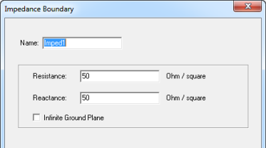
The default Resistance and Reactance are 50 Ohms per square.
If you want to create a boundary that demonstrates spatial dependence, you must first assign that boundary to a sheet object. Then to define a spatial dependence for the boundary, you can create an expression for resistance or reactance using x, y, or z. For example, 50+y.
- Select Infinite Ground Plane if you
want the surface to represent an electrically large ground plane when
the radiated fields are calculated during post processing. .
Note:
If you select Infinite Ground Plane, the effect of the impedance boundary will be incorporated into the field solution in the usual manner, but the radiated fields will be computed as if the lossy ground plane is perfectly conducting. Only one infinite ground plane is permitted in designs with impedance boundaries
Note:You can assign a variable as the resistance and reactance values. Eigenmode designs cannot contain design parameters that depend on frequency, for example, a frequency-dependent impedance boundary condition.