
HFSS Getting Started Guides
General Guidance
In addition to the Getting Started with HFSS guides listed further down in this topic, the following general HFSS documentation is available:
- HFSS Scripting Guide
- An Introduction to HFSS
- HPC Administrator's Guide
- An Introduction to Multi-Frequency Adaptive Meshing in HFSS
Getting Started with HFSS
The following guides are tutorials covering various types of HFSS designs. These Getting Started guides typically walk you through the steps to build the geometry, set up the solution, run the analysis, and evaluate the results (by generating plots, overlays, and animations):
- 20 GHz Waveguide Combiner
- Ball Grid Array IC Package
- Bandpass Filter
- Bow Tie Antenna
- Parametric Method: Makes use of advanced 3D Modeler commands
- Linear Method: The traditional approach of creating the antenna in a "linear" fashion
- Antenna Design Toolkit: Automatically generates the antenna in a ready-to-solve state
- Cable Modeling
- Coax Connector
- Coax Tee
- Dielectric Resonator Antenna
- Floquet Ports
- Keyboard Shortcuts
- Shortcut keys (either predefined or user-defined)
- Keystroke sequences for menu bar navigation to trigger desired actions
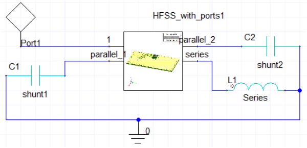
- Matching Network – Using Tuning in Circuits
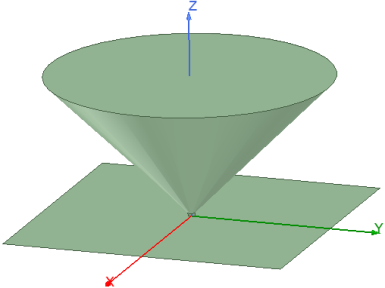
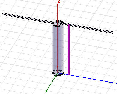
- Monocone Antenna
- Monostatic RCS using SBR+
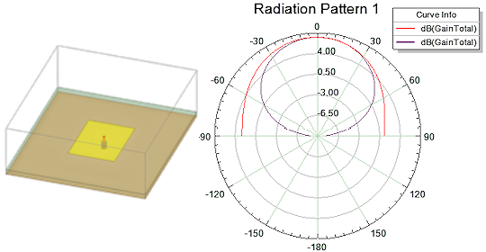
- Probe Feed Patch Antenna
- Radar Cross Section
- RCS Test Model (Ogive)
- Ridged Horn Antenna
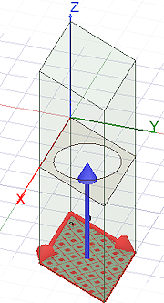
- Silicon Spiral Inductor
- Skin Depth Seeding
- TDR for Coax Bend
- Ultra High Frequency Probe
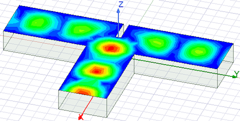
- Waveguide T-Junction
- Waveguide T-Junction Optimization
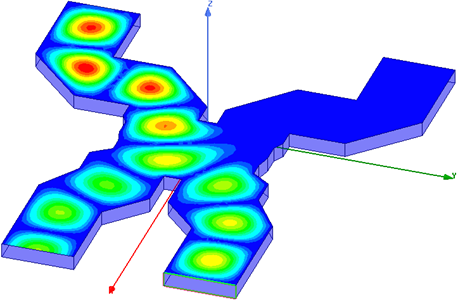
This Getting Started Guide describes how to set up and solve a two-way, low-loss waveguide combiner.
This Getting Started Guide is written for HFSS Transient beginners as well as experienced users who are using HFSS for the first time. This manual guides you through the setup, solution, and analysis of a transient simulation.
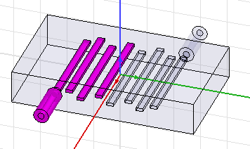
This Getting Started Guide assumes some familiarity with HFSS. It guides you through the process of creating a bandpass filter. It includes the use of Duplicate Around Axis commands.
This design has a frequency sweep. If you want to distribute the solutions of the frequencies for efficient simulation, you can use High Performance Computing (HPC). The HPC options are discussed in this guide. For more information about how to set up HPC, see the Add HPC Analysis Setup section in the Getting Started Guide for Bandpass Filter. You can access the design from the Examples folder, which also contains a short description on the HPC setup in the associated PDF.
This Getting Started Guide contains three separate tutorials that show you how to create a coplanar, waveguide-fed, bow tie antenna in Ansys HFSS. There are multiple ways to create and solve designs in HFSS. A bow tie antenna is a simple design that can be created using any of the following methods:
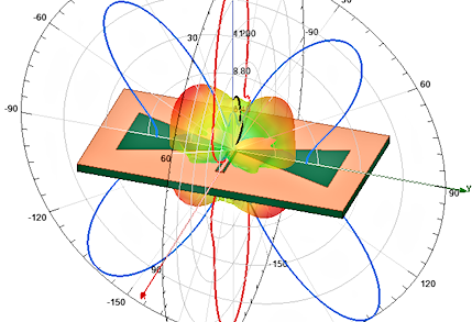
The first tutorial covers the parametric method, the second one covers the "linear" method, and the third one covers the automatic method of creating the antenna. You will create 2D plots of the radiation pattern and create a 3D gain plot (far field pattern). You will also overlay the 3D gain plot and the 2D radiation pattern plots on the model geometry.
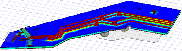
This Getting Started Guide covers the cable modeling workflow. You can now complete the entire cable modeling workflow within a single HFSS design. Cables are defined as 3D components. Required 2D Extractor and Circuit simulations are set up and run automatically in the background as part of the HFSS solution process. No manual setup, linking, or transfer of data is required on the analyst's part.
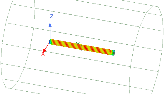
This Getting Started Guide assumes some familiarity with HFSS. It guides you through the process of creating a coax connector. This includes the use of relative coordinate systems as an aid to building the model. It also uses Boolean and sweep operations.
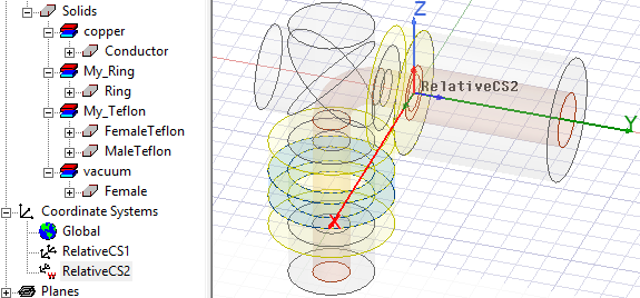
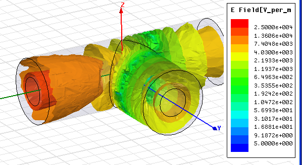
This Getting Started Guide is suitable for beginners and advanced users. It includes instructions to create and solve a Coax Tee and evaluate the results of the simulation (including creating an S-parameters vs. Frequency plot and an E-Field overlay). The E-Field is overlaid on the Coax Dielectric, which is modeled as a vacuum region surrounding the Coax Center Pin.
This Getting Started Guide is written for Ansys Electronics Desktop beginners as well as experienced users who are using HFSS for the first time. This guide leads you step-by-step through creating, solving, and analyzing the results of a dielectric resonator antenna.
This Getting Started Guide is intended as supplementary material to HFSS users. We assume you have some experience designing projects using HFSS. The document includes instructions to create, solve, and analyze results of models that are excited with Floquet ports.
By following the steps in this guide, you will learn how to set up Floquet ports in Ansys Electronics Desktop.
For those who prefer communicating instructions using a keyboard more often than a mouse, this Getting Started guide presents two different techniques for working with Ansys Electronics Desktop:
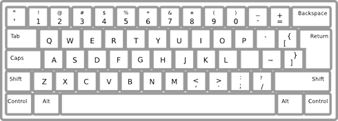
This guide shows you how to create, simulate, and analyze a probe fed, slot coupled patch antenna using the HFSS design environment, with an emphasis on using keyboard shortcuts to complete the work.
In this Getting Started Guide, you will learn about dynamic linking capabilities between HFSS and Circuit designs in the Ansys Electronics Desktop application. Specifically, the guide provides an example of a matching network for a Bluetooth chip antenna.
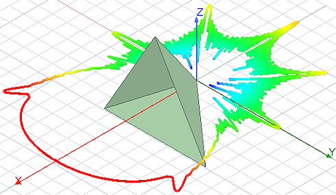
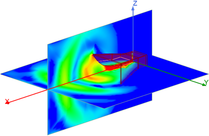
This Getting Started Guide looks at the radiation pattern from a monocone antenna using the HFSS design type with an IE hybrid region applied to the model objects. An IE Region results in a fullwave Integral Equation solver being used to analyze the model. This solver is particularly well suited for analyzing large conducting objects, and it eliminates the necessity of creating an open region (that is, a vacuum or air box) around the model to determine far field effects.
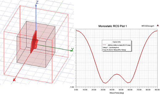
This Getting Started Guide describes how to use HFSS to model a Monostatic Radar Cross Section (RCS) of a metal trihedral reflector using an SBR+ Hybrid Region.
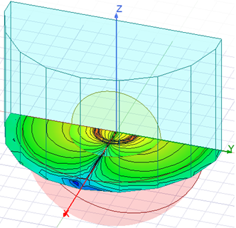
This Getting Started guide assumes some familiarity with HFSS. It includes the use of Perfect E and Radiation boundaries and a Radiation Pattern plot.
This guide shows how to create and solve a model for computing a radar cross section (RCS).
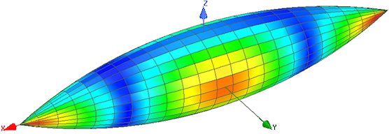
This Getting Started Guide looks at the scattering from a standard Radar Cross Section (RCS) test model (specifically, the ogive) using the HFSS design type with an IE region assigned to the ogive. An IE region results in a full-wave Integral Equation solver being used to analyze the model. This solver is particularly well suited for analyzing large conducting objects, and it eliminates the necessity of creating an open region (that is, a vacuum or air box) around the model to determine far field effects.
This Getting Started Guide is written for HFSS Transient beginners as well as experienced users who are using HFSS for the first time. This manual guides you through the setup, solution, and analysis of a transient horn antenna problem.
By following this guide, you will learn how to set up HFSS transient antenna problems.
This Getting Started guide assumes some familiarity with HFSS. It includes the use of Perfect E and Radiation boundaries and Output Variables in generating plots.
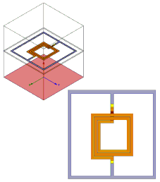
Related Topic: Application Specific Modeling Guide: Spiral Inductors on Silicon Substrate
By following the steps in this guide, you will learn to use Skin Depth-Based mesh refinement for HFSS or Maxwell Modelers to specify a number of layers and a skin depth as an alternative to modeling physical layers.
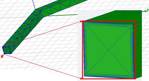
The guide also shows how to use mesh plots with cut planes, as well as a repurposed Model Analysis dialog to view and obtain statistics on layering success.
This Getting Started Guide is written for HFSS Transient beginners as well as experienced users who are using HFSS for the first time. This manual guides you through the setup, solution, and analysis of a time delayed response problem for a coax bend.
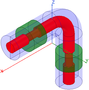
By following this guide, you will learn how to set up HFSS transient problems.
This Getting Started Guide assumes some familiarity with HFSS. It includes the use of boolean operations and the use of a ground plane and radiation boundaries.
This Getting Started Guide is written for Ansys Electronics Desktop beginners as well as experienced users who are using the HFSS design type for the first time. This guide will lead you step-by-step through creating, solving, and analyzing the results of a T-shaped waveguide with an inductive septum. This type of structure is used to split an incoming microwave signal into two outgoing signals. The waveguide's transmission and reflection of the signal will depend on the position of the septum.
This Getting Started Guide is written for Optimetrics beginners as well as experienced users who are using Optimetrics for the first time. You must have completed Getting Started with HFSS: A Waveguide T-Junction before you begin this guide. The guide also shows how to import the Tee Geometry to SpaceClaim, and link it to HFSS for parameterization and optimization.
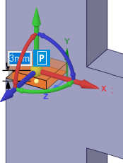
You will use Ansys Electromagnetics Optimetrics software to find an optimal position for the septum. Prior to performing the optimization, you will set up and solve a parametric analysis.