Net Tracing in IC Mode
The GDSII file format does not directly support the concept of nets. When Electronics Desktop imports a GDSII file, it creates nets based on the placement of geometries, cells, cell references, and input from the GDSII file’s control file text (e.g., text in GDS_CELL_RULES > BLACK_BOX_CELLS and GDS_NET_DEFINITIONS). The Net Tracing feature uses the control file text to populate the Net Tracing window.
Net Tracing identifies the primitive that encapsulates the text’s location (i.e., the seed text), then searches for any primitives that are physically connected to the seed text and adds them to the net. Then Net Tracing searches for primitives that are physically connected to those newly added primitives. This process continues until all physically connected primitives are identified and added to the net.
Only the control file can provide seed text for net tracing. New seed text cannot be added in IC Mode.
Complete these steps to access the Net Tracing window.
- From the Layout tab, click Net Tracing.

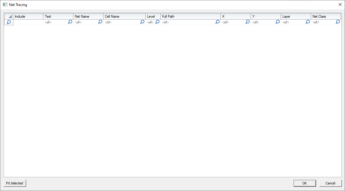
The Net Tracing window opens and displays a list of all potential nets and columns of relevant data.

- Include - whether or not net tracing is performed on this text object (i.e., check or uncheck)
- Text - origin text for the net
- Net Name - name applied to the net if/when it is created
- Cell Name - name of the cell the text is in
- Level - level of the net in the design hierarchy
- Full Path - specific location of the net in the design hierarchy
- X - x coordinate of the starting text
- Y - y coordinate of the starting text
- Layer - layer the starting text is on
- Net Class - name of a group of associated nets
- Decide which nets to create and check their adjacent boxes in the Include column.
- Click OK to close the window. All Included nets are created and their starting text is deleted from the cell. Any remaining text can be used again.
