Nonlinear roll damping moment can be calculated in Time Response and Frequency Statistical analyses to take into account the effect of vortex shedding from the bilges and bilge keels of a vessel.
To add Nonlinear Roll Damping properties:
Select a Part in the tree view.
Right-click the Part and select Add > Nonlinear Roll Damping, or click the Nonlinear Roll Damping icon in the Parts toolbar.
Select the Nonlinear Roll Damping object in the tree and set the properties.
The method for bilge vortex shedding is based on "An Engineering Assessment of the Roll of Non-linearities in Transportation Barge Roll Response," Robinson and Stoddart, Trans. R.I.N.A., 1986.
The method for bilge keel roll damping is based on "ITTC recommended procedures 7.5-02-07-04.5 - Numerical estimation of roll damping", 2011.
Whether vortex shedding is occurring or not is calculated by the program based on the relative flow velocity at the bilge, Keulegan-Carpenter number, roll natural frequency of the vessel, and the radius of the bilge. The roll damping coefficient used in the nonlinear roll damping force calculation is also calculated by Aqwa based on a database stored within the program.
To compute the effects of nonlinear roll damping, select one of the following options from the Nonlinear Roll Damping drop-down menu:
Use a Coefficient
Define Bilge Parameters
Combine Coefficient and Bilge Parameters
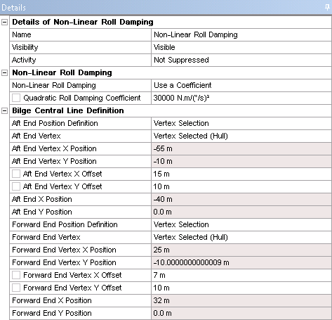
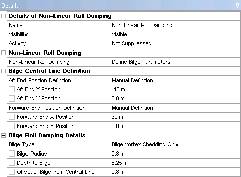
For all three options, you must define an axis on which the damping moment is applied. A central line must be defined by an Aft End Position and a Forward End Position; each has an End Position Definition which can be switched between Vertex Selection and Manual Definition. If the End Position Definition is set to Vertex Selection, you should select an End Vertex from the geometry and (optionally) define the End Vertex X Offset and End Vertex Y Offset. The End X Position and End Y Position will be read-only. If the End Position Definition is set to Manual Definition, you should enter the End X Position and End Y Position directly.
When defining a coefficient (Use a Coefficient or Combine Coefficient and Bilge Parameters), use the Quadratic Roll Damping Coefficient field.
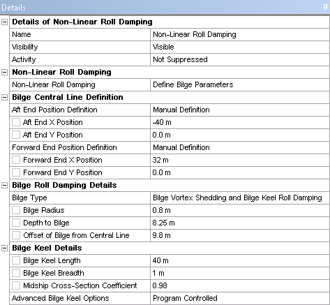
When defining bilge parameters, it is assumed that the two bilges have symmetric properties about the center line of the vessel. The Bilge Type field allows you to control the type of damping calculated. By default, this field is set to Vortex Shedding Only. You can also select Bilge Vortex Shedding and Bilge Keel Roll Damping to calculate the roll damping effects of the bilge keel. The Bilge Radius defines the local radius of the bilge corner. The Depth to Bilge is the vertical position of the bilge corner on the vessel in the global axis system. The Offset of Bilge from Central Line is the lateral offset of the bilge corner from the center line of the vessel in the global axis system.
Note: When an End Position Definition is set to Vertex Selection, the vertical position of the vertex selected for that central line end point is irrelevant; the vertical position of the central line is always set by Depth to Bilge.
If you set Bilge Type to Bilge Vortex Shedding and Bilge Keel Roll Damping, the Bilge Keel Details submenu becomes available. You can set the Bilge Keel Length and Bilge Keel Breadth. Changing Advanced Bilge Keel Options to Manual Definition allows you to set the Draft of Vessel and Breadth of Vessel.