Create a Links toolkit object for each sprocket as shown below:
Select the Model element in the Project tree.
From the Motion ribbon, click and select .
Under Motion in the project tree, right-click the new Path object and rename it as
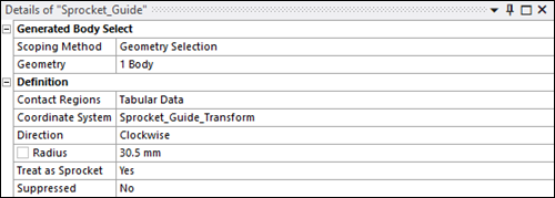
Sprocket_Guide.In the Details panel, verify that the Scoping Method is set to
Geometry Selection.Using the selection tool, select the Sprocket_Guide body and click in the Geometry field.
Under Definition, click in the Contact Regions field (where is says Tabular Data).
Ensure that the Contact Regions list contains the Named Selection titled
Sprocket_Guide_Surfaceand click .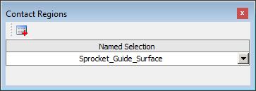
Set the Coordinate System for the path to
Sprocket_Guide_Transform.Set Direction to
Clockwiseand Radius to30.5 mm.Set Treat as Sprocket to
Yes.Verify that the Details panel for the completed Path appears as below.
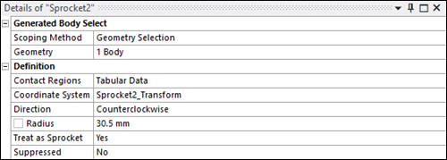
Repeat steps 1 to 10 above to create two additional Path objects for
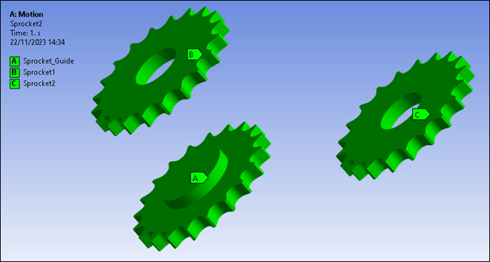
Sprocket1andSprocket2. These objects should both be defined with a Radius of30.5 mmand with Direction set toCounterclockwise. The completed paths should appear as shown below.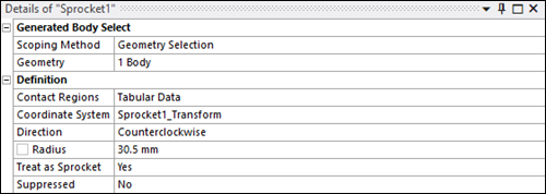
You have now defined a complete set of sprocket paths.
Now, create a Links toolkit Segment object for each chain link as described below:
From the Motion ribbon, click and select .
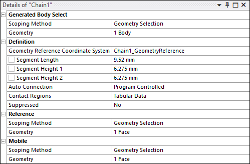
Under Motion in the project tree, right-click the new Segment object and rename it as
Chain1.In the Details panel, verify that the Scoping Method is set to
Geometry Selection.Using the selection tool, select the Chain1 body and click in the Geometry field.
Set the Geometry Reference Coordinate System to
Chain1_GeometryReference.Set the segment geometry as follows:
Segment Length :
9.52
                                    mm
Segment Height 1 :
6.275
                                    mm
Segment Height 2 :
6.275
                                    mm
Click in the Contact Regions field and ensure that the dialog contains the Named Selection titled
Chain1_Contact.In the Details panel, under Reference, ensure that Scoping Method is set to .
Under Reference, click in the Geometry field. Using the selection tool, select the first link pin and click .
In the Details panel, under Mobile, ensure that Scoping Method is set to .
Under Mobile, click in the Geometry field. Using the selection tool, select the second link pin and click .
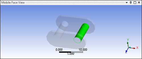
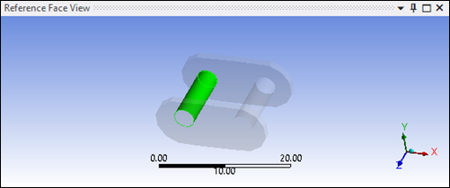
The defined reference (red) and mobile (blue) geometries should now appear in the graphical display as shown below.

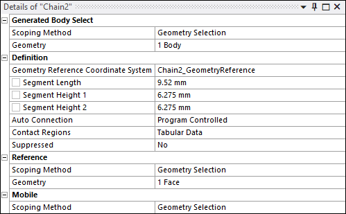
Repeat steps 1 to 11 above to create another Segment object for
Chain2, using the same dimensions as .The completed segments should appear as shown below.