Overhang features, or simply "overhangs," are unsupported solid features that rise in the build direction when using Additive Manufacturing (AM) processes. They are mainly related to the printing angle, but other factors, such as feature length, may also be included.
Available for the Mixable Density, Density Based, and Level Set Based optimization methods, the AM Overhang Constraint manufacturing constraint aims to create self-supporting designs that prevent the formation of these overhanging regions.
Go to a section topic:
Overview
For any AM process, support structures can lead to excessive printing time and cost [15]. More precisely, for metal powder bed fusion processes, overhang features can significantly impact the structural quality of the printed part. For fused deposition modeling (FDM) processes, the existence of supports may significantly deteriorate the quality of the outer surface, having a strong visual impact on the printed part, as illustrated below.
![Printing Angle Impact on Quality of Surface in FDM [15].](graphics/gds_topo_man_const_overhang1.png)
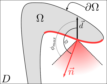
In theory, the computation of the overhang angle constraint is performed in two steps:
The inner product
 between the exterior normal vector and the build direction
is computed for every point of the structural boundary.
between the exterior normal vector and the build direction
is computed for every point of the structural boundary.The minimum value of
shall be greater than the threshold provided by the angle
 . That is:

However, the above formulation presents two drawbacks:
It is not derivable due to the minimum operator and therefore not suitable for gradient-based optimization algorithms.
It is not applicable for all methods, mainly because it requires geometric information that is not directly available for the density-based methods.
The devised formulation depends on the Structural Optimization framework described in the following table.

Setup and Technical Details
The setup requires specifying a Build Direction
( ) and the Overhang Angle (
 ).
).
Table 4.2: Setup Parameters and Technical Details
| Mixable/Density Based Method | Level Set Based Method | |
|---|---|---|
|
|
27° | |
|
Exclusion Region |
You can decide whether to Include or Exclude Exclusions from the Analysis Settings. |
Exclusion regions are inherently considered in the overhangs evaluation. |
|
Working Domain |
All boundaries of the working domain that are not self-supported are considered as print beds. Namely, they are ignored by the constraint. | |


Recommendations and Observations
For the Level Set Based optimization method, the angle limit may still be violated along sharp lines, where the normal vector is not accurately defined (see illustration for Y axis overhang) [16]. Such shapes require linear supports during the printing process, that is, supports along some two dimensional curve of the print bed.
As with any constraint, the AM Overhang Constraint affects the objective performance. Namely, by increasing the allowed overhang angle (
 ), the feasible domain shrinks and likely results in
smaller objective gain.
), the feasible domain shrinks and likely results in
smaller objective gain.
Example
This example examines the effect of an AM Overhang Constraint Manufacturing Constraint on an engine bracket model.
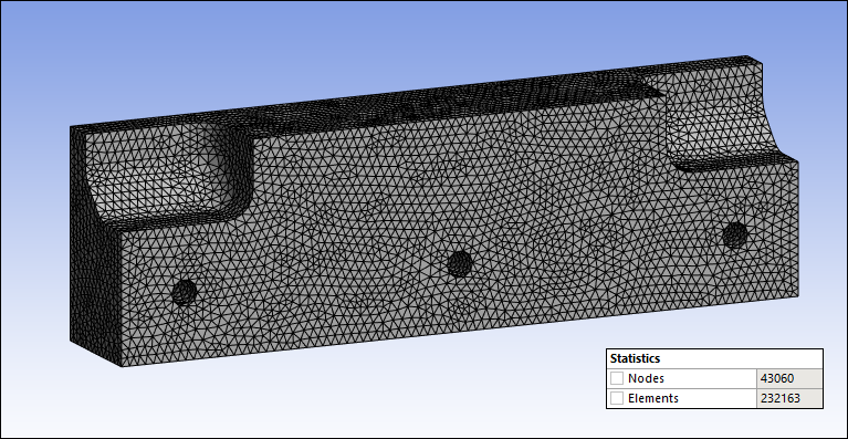
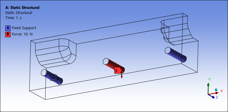
- Set Up and Mesh
The specified mesh and the setup of the environment, shown in wireframe mode so that you can clearly see the specified boundary conditions, are illustrated below. The optimization problem is to minimize the structural compliance under a volume fraction constraint of 0.4.
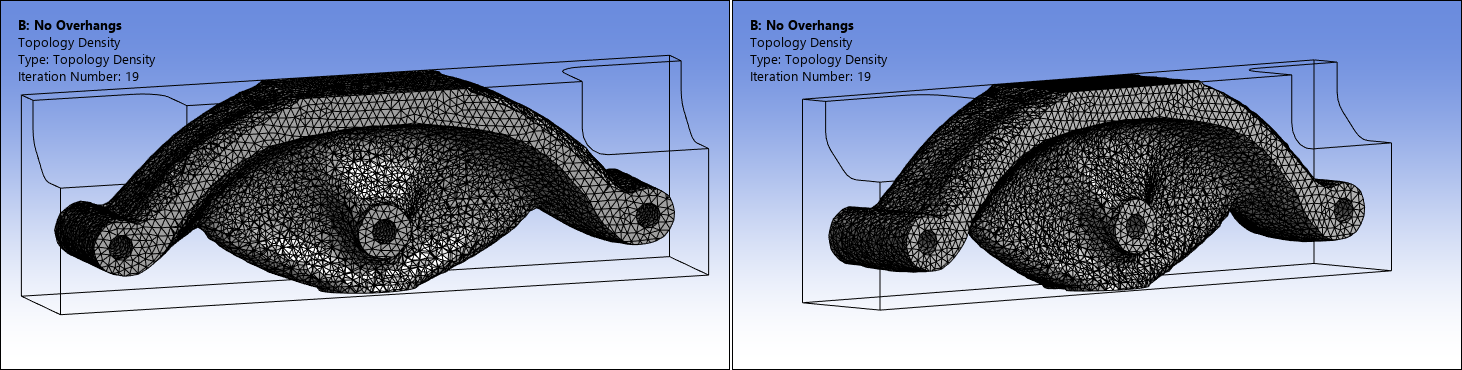
- No AM Overhang Constraint
Here are illustrations of the optimized result without considering an AM Overhang Constraint. The structural compliance equals 1.29836e-07.
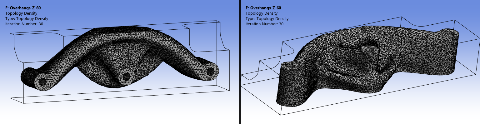
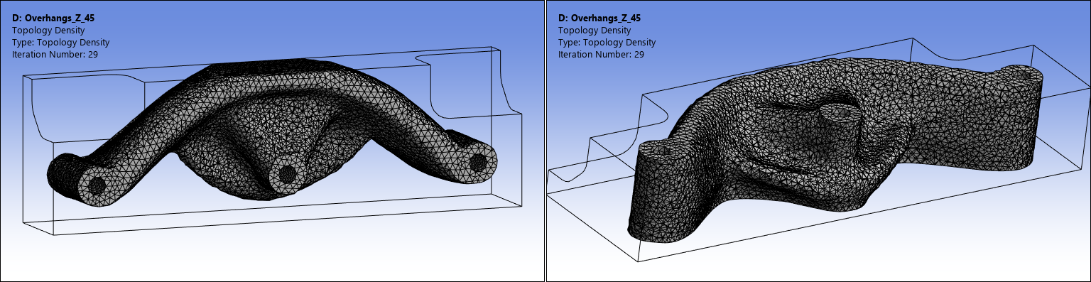
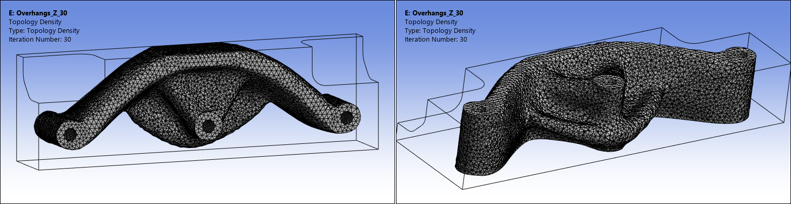
- AM Overhang Constraint Z Axis
In the following, an AM Overhang Constraint is added for a build direction in the positive Z axis (
 ) and for varied overhang angles (
 = 60°, 45°, and 30°). The structural
compliance is increased by +7.4%, +6.3%, and +5.7% respectively and, as
expected, increasing the overhang-angle results in less objective
gain.
= 60°, 45°, and 30°). The structural
compliance is increased by +7.4%, +6.3%, and +5.7% respectively and, as
expected, increasing the overhang-angle results in less objective
gain.AM Overhang Constraint + Z 60°
AM Overhang Constraint + Z 45°
AM Overhang Constraint + Z 30°
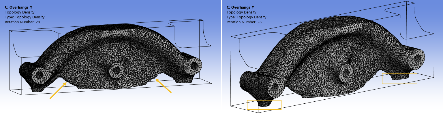
- AM Overhang Constraint Y Axis
In the following, an AM Overhang Constraint is added for a build direction in the positive Y axis (
 ) and for an overhang angle of
  = 45°. The structural compliance equals
1.32978e-07 (+2.4%). Overhanging regions are removed, and the shape
appears to be self-supporting. However, as shown, this is achieved by
forming linear overhangs and using some material as supports for the 3D
printing. This indicates that the choice of build-direction is not
appropriate.
= 45°. The structural compliance equals
1.32978e-07 (+2.4%). Overhanging regions are removed, and the shape
appears to be self-supporting. However, as shown, this is achieved by
forming linear overhangs and using some material as supports for the 3D
printing. This indicates that the choice of build-direction is not
appropriate.