The fogging / defogging model in ICE3D is designed to simulate fog and frost accumulation on cold surfaces like windshields, pipes, HVAC components, etc., and their removal with unsaturated airflow which is the typical method employed for automobile windshields. To use this model, a vapor transport solution calculated with DROP3D needs to be provided to ICE3D with the airflow solution.
The vapor transport model of DROP3D is able to calculate water vapor condensation rate on walls, based on their temperature provided in the air flow solution, local saturation and actual vapor pressures. This rate is used as water collection rate in ICE3D to integrate in time the accumulation of fog and frost on walls. For walls with temperatures below 0 C, it is assumed that the accumulation is in frost state. The energy equation in ICE3D is then used to calculate the heat released to the walls due to this phase change. This heat flux is stored in the Anti-icing heat flux solution field which is the standard storage for conductive heat flux from walls.
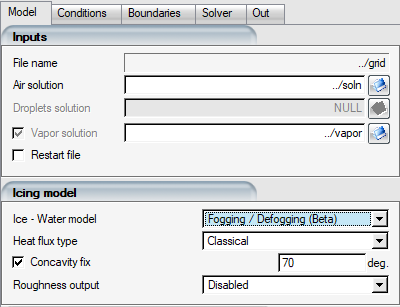
To use this model, select it from the drop-down menu. Once selected, the Droplets solution file selection box will be grayed out since only vapor solution is needed for this simulation. There are no other settings specific to this model in ICE3D, rest of the configuration can be carried out the usual way.
To complete a defogging simulation, ICE3D needs to restart from a swimsol file that has been produced by a prior fogging simulation. The total condensation amount will be available in film height field if the walls are above freezing, or ice growth field if they are below freezing.
Example 1.1: Fogging and Defogging of Small Aircraft Cabin Windows
The following figures show an example application of the model using the cabin of a small aircraft with five occupants. The air and vapor solutions are solved for the interior of the cabin, where the cabin walls are set as adiabatic and windows are set to T = -10C assuming this would be the ambient exterior temperature around the cabin. Humid air is provided from inlet boundary conditions located where the mouths of the occupants would be. The air + vapor coupled simulation is run in steady-state until convergence, and vapor condensation rates are established on the windows. It is assumed that the latent heats of phase change due to condensation on windows are quickly removed with the airflow surrounding the cabin, maintaining the -10C condition.
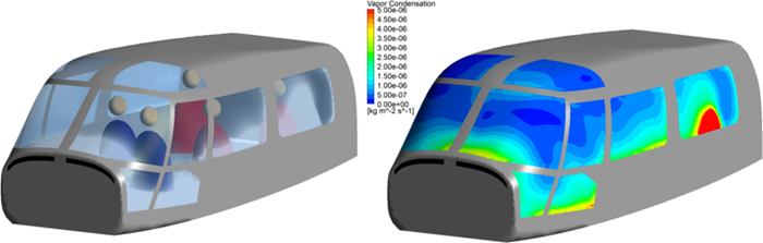
Figure 1.2: Transparency Loss Due to Fogging (Left) and Vapor Condensation Rate (Right) Displayed on the Windows of a Helicopter Cabin
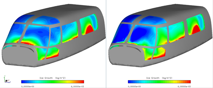
For defogging, a new air+vapor coupled solution is restarted from this state, this time introducing hot air flow with low humidity at the vents (shown in black in above figure) at the front of the cabin. The change in local vapor pressure, saturation pressure, and heat transfer coefficients promote evaporation of the previously accumulated frost in the restarted ICE3D solution file. The following figures show the amount of ice accumulated in terms of frost for the first 30 minutes before the hot air vents are activated (left), and the remaining frost after the vents are turned on. The forward windows are mostly cleared while the side windows continued to accumulate frost since the warm air was not directed towards them.
Figure 1.3: Frost Accumulation per Area After 30 Minutes of Condensation With the Vents off (Left) and 30 Minutes After the Vents Have Been Turned on (Right)