In addition to the simplified heat sink described above, Ansys Icepak provides a detailed heat sink, which is intended for use in the design of heat sinks.
Detailed heat sinks are designed to model finned heat sinks or heat sinks with pins. They consist of a base, fins or pins, and (optionally) a thermal interface resistance that models the heat transfer from the fins or pins through the base of the heat sink to any object connected to the base.
There are four types of detailed heat sinks available in Ansys Icepak:
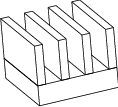
Extruded heat sinks consist of a base and fins that run parallel to each other across the length of the base. You specify the number of fins, their dimensions, and the direction in which the fluid will flow across the base. An example of an extruded heat sink is shown in Figure 24.2: Extruded Heat Sink.
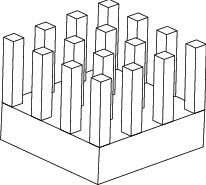
Cross cut extrusion heat sinks have rectangular fins separated from each other in both directions parallel to the base. You specify the number of fins in the two directions parallel to the plane of the base, and the dimensions of the fins. An example of a cross cut extrusion heat sink is shown in Figure 24.3: Cross Cut Extrusion Heat Sink.
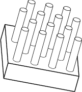
Cylindrical pin heat sinks have cylindrical or tapered pins separated from each other in both directions parallel to the base. You specify the number of pins in the two directions parallel to the plane of the base, and the dimensions of the pins. The pins can be in-line or staggered. An example of a cylindrical pin heat sink is shown in Figure 24.4: Cylindrical Pin Heat Sink With Staggered Pins.
Bonded fin heat sinks have the same type of geometry as extruded heat sinks. For a bonded fin heat sink, you can specify a contact resistance between the base of the heat sink and the fins.