


Coupling lines
Coupling lines are used in design problems where there are multiple limiting constraints - that is, failure may occur by more than one mechanism.
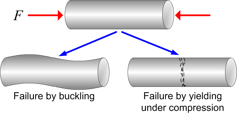
For example, a rod loaded in compression may fail by buckling, or by direct compressive failure. Coupling lines allow both failure modes to be considered in the selection process, and enable the dominant failure mode to be identified for a given material choice.
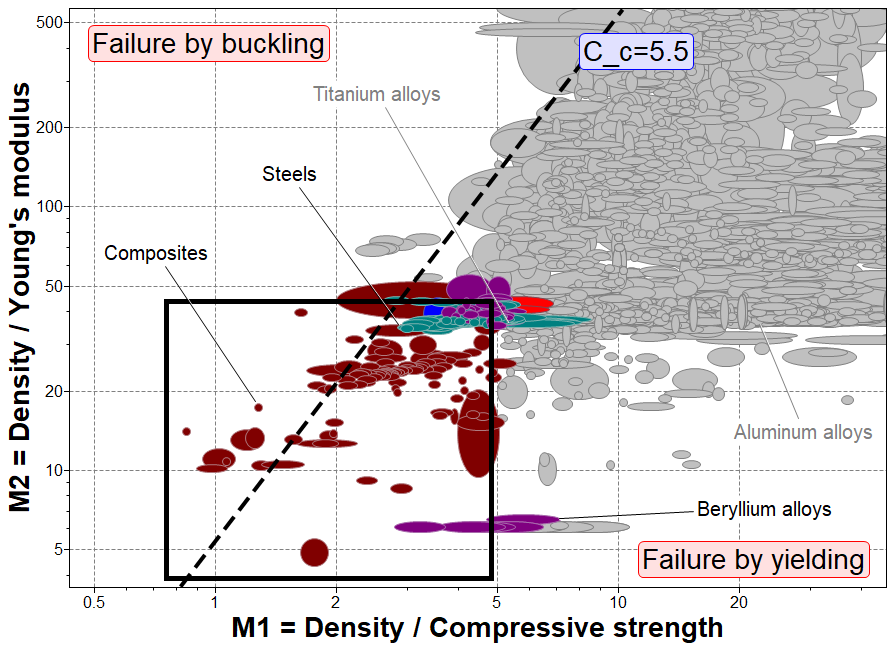
An example coupling line chart is shown above. This considers the case of a hollow piston rod loaded in compression. The length and outer radius of the rod are fixed. The objective is to minimize the mass, and the limiting constraints are that it must not fail by elastic buckling or direct compressive fracture.
The performance indices for both limiting constraints are plotted on the chart axes. The coupling line represents the point where the failure mode switches from one mode to the other. Materials above the coupling line will fail by buckling and those below will fail by compressive fracture. Materials on the line are equally likely to fail by buckling or yielding.
The position of the coupling line is determined by the geometric variables that are fixed by the design. In this case, the fixed variables are the rod length and the outer radius.
Material selection is performed by creating a selection box and moving it along the coupling line to reduce the number of selected materials. Suitable materials are found in the bottom left of the chart if the aim is to minimize the performance indices, or in the top right of the chart if the aim is to maximize the performance indices.