Ansys Sherlock has the capability to model various types of heat sinks in addition to the PCB, components, and mount points for Finite Element Analysis (FEA) purposes. Heat sinks are modeled with a set of properties defined in the layer viewer. Once added to a circuit card assembly (CCA), these heat sinks are used during analysis. Heat sinks may optionally be attached to mount pads which are attached to the PCB.
In this section, the following topics are covered:
The Sherlock analysis modules make use of the following properties for heat sink modeling.
Table 8.28: Heat Sink Modeling Properties
| Heat Sink Layout | Heat Sink Material | Heat Sink Units |
| Heat Sink Length | Heat Sink Width | Heat Seat Thickness |
| Heat Sink Fin Height | Heat Sink Fin Width | Heat Seat Fin Thickness |
| Heat Sink Length Fin Pitch | Heat Sink Width Fin Pitch | Heat Sink Fin Bend |
| Heat Sink Fin Shoulder | ||
The Heat Sink Layout property defines the basic shape of a heat sink. Supported values are:
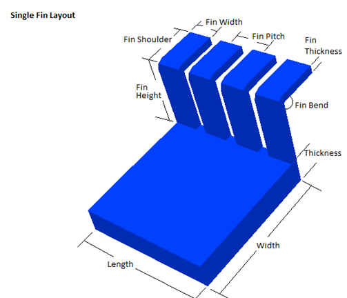
Single Fin – heat sink with a single row of fins along the length of one edge of the heat sink base. Fins may be vertical or have a bend up to 90 degrees. The number of fins is governed by the length of the heat sink base, the fin length pitch, and the fin width.
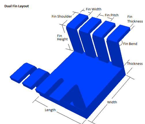
Dual Fin – heat sink with two rows of fins, each along the length of one edge of the heat sink base. Fins may be vertical or have a bend up to 90 degrees. The number of fins is governed by the length of the heat sink base, the fin length pitch, and the fin width.
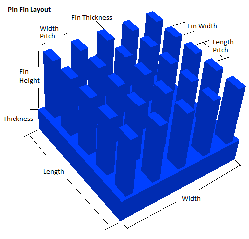
Pin Fin – heat sink with one or more rows and columns of fins. The number of fins along the length of the heat sink is governed by the length of the heat sink, the fin length pitch, and the fin width. The number of fins along the width of the heat sink is governed by the width of the heat sink, the fin width pitch, and the fin thickness.
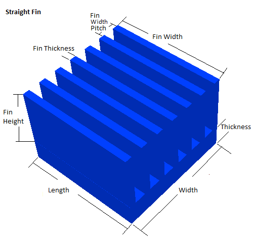
Straight Fin – heat sink with one or more rows of fin blades. The length of the fin blades is governed by the fin width. The number of fins is governed by the width of the heat sink, the fin width pitch, and the fin thickness.
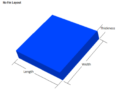
No Fin – heat sink with no fins or fin blades.
Heat sinks are modeled based on a set of properties. The following properties define how a given heat sink layout is modeled.
Heat Sink Length: Length of the heat sink (usually maximum dimension).
Heat Sink Width: Width of the heat sink (usually minimum dimension).
Heat Sink Thickness: Thickness (height) of the heat sink base.
Heat Sink Fin Bend: Indicates how far the heat sink fin is bent from vertical in degrees. When set to zero (0), the fin will be straight and vertical. When greater than zero, the fin will be modeled by a lower vertical segment and an upper shoulder segment that is bent from vertical by the specified amount. The length of the vertical segment is specified by the Heat Sink Fin Height property, while the length of the shoulder segment is specified by the Heat Sink Fin Shoulder property.
For Single-Fin and Dual-Fin layouts, the angle may be between 0 and 90 degrees (inclusive). For all other layouts, the angle must be 0 degrees.
Heat Sink Fin Height: Height of the heat sink fin for straight fins and the length of the vertical segment of bent fins. For bent fins, the height specifies the location where the center of the shoulder segment intersects the vertical segment.
Heat Sink Fin Width: Width of the heat sink fin (usually the maximum dimension).
Heat Sink Fin Thickness: Thickness of the heat sink fin (usually the minimum dimension).
Heat Sink Length Fin Pitch: The center-to-center distance between adjacent fins along the length of the heat sink.
Heat Sink Width Fin Pitch: The center-to-center distance between adjacent fins along the width of the heat sink.
Heat Sink Fin Shoulder: The length of the non-vertical fin segment for bent fins.
Heat Sink Material: Primary material of which the heat sink is made. Material names are defined in the material data file provided by Sherlock and/or a user-defined data file.
Heat Sink Units: Unit of length for all sink measurement properties.
Weight: The estimated heat sink weight is displayed when viewing heat sink properties. This is a read-only field only intended for reference.
Heat sinks are added in the Layer Viewer. Using the ODB++ Tutorial example, select Edit Heat Sinks from the Edit menu of the Layer Viewer. The Heat Sink Editor will now be indicated along the bottom of the Layer Viewer.
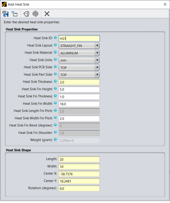
To add a heat sink, right-click one an area on one of the components displayed and select Add Heat Sink. This will display the Add Heat Sink dialog.
This dialog allows for the definition of all the properties that define the location of the heat sink and the properties of the heat sink. When adding a heat sink to a component, the default length and width values of the heat sink will be the same as the part.
Heat sinks may be placed on top of or underneath of parts. When placing underneath of parts, typically select either the single-fin or dual-fin heat sink layout as these two layouts line the fins along the outside of the edge of the heat sink.
To view a definition of each of the heat sink properties along with a diagram of how each is defined for every heat sink layout, click the question mark next to the desired property.
To add this heat sink, click the Save the changes and exit the editor button in the dialog.
 Save the changes and exit the editor
 Reset the form to the currently saved values
 View the 3D model of the heat sink
 Refresh the 3D model
 Close the dialog
Links to subsections:
In the layer viewer, verify the Heat Sinks folder is opened in the Layers menu and the desired side of the PCB is selected to see all heat defined heat sinks. Similar to other layer viewer editors, right-click the heat sink to be modified, then select Edit Properties from the context menu. The same dialog is presented for updated properties as is created for adding heat sinks.
From the context menu, you may also select to move the heat sink which will allow you to reposition the heat sink by using the mouse to move the heat sink to the desired location. You may rotate the heat sink one of the predefined offsets. Adjustments to the rotation other than 45 and 90 degree increments may be made from the heat sink properties dialog. You may copy the heat sink, which will result in an identical heat sink created and located next to the existing heat sink. You may delete the heat sink. When you are complete with the Heat Sink editor you must Save or Apply any changes for them to take affect.
Multiple heat sinks may also be selected and the properties of those heat sinks updated at the same time. When the properties for more than one heat sink are edited at the same time, any heat sink property which varies between the selected heat sinks will display the value <VARIOUS>. Any field which is left as the value <VARIOUS> when saving the form will leave the original heat sink value specified for that given field. Any other field values will be assigned to all selected heat sinks.
Heat sinks may be located over top of mount points defined as mount pads or standoffs. When a heat sink is located over top of these mount points heat sink attachment points may be created between the heat sink and the mount point. To add an attachment point to a heat sink, place the heat sink over top of a mount point using the Heat Sink Editor in the Layer Viewer. Now make sure no heat sinks are selected, then right-click a mount point that should become an attachment point for the heat sink. If the mount point meets all the properties to become an attachment point, then a context menu should appear to add the selected mount point as a heat sink point. Repeat this process for each of the desired mount points. To remove a mount point as a heat sink attachment point, right-click the mount point and select Remove Heat Sink Point.
Attachment points for heat sinks must adhere to the following conditions:
Attachment points attach the heat sink to the PCB
Attachment points must be fully contained by the heat sink outline
Attachment points may not intersect or be contained by any part outline
Attachment points may not be defined when a heat sink is under a part
All attachment points assigned to a heat sink must have the same height
Attachment points on heat sinks covering a part must be at least as tall as the height of the part
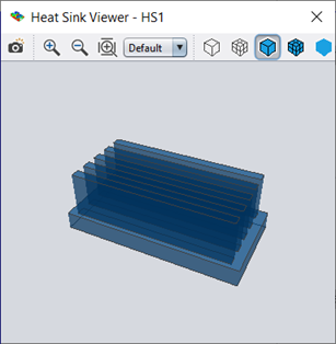
From the heat sink editor dialog, click the View the 3D Model of the Heatsink icon to launch a 3D representation of the heat sink as defined in the dialog. You may also right-click the heatsink in the Layer Viewer and select View 3D Model. To quickly see how changes to the heat sink properties in the Heat Sink Editor affect the model, click the Refresh 3D Model icon. Be aware, however, that you cannot view the 3D model when editing multiple heat sinks simultaneously, as their properties will vary.
Heat sinks can be selectively enabled/disabled in any FEA generated using any of the following menu options:
Generate 3D Model
Export FEA Model
Edit Analysis Properties
In all cases, the Heat Sinks property tab is used to specify the following heat sink analysis properties:
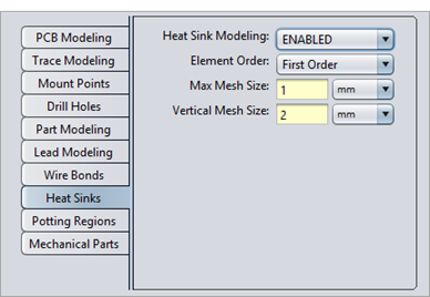
The Element Order property specifies the type of FEA elements to use when modeling the heat sink. First order elements reduce analysis complexity and run time, but may not result in the most accurate results, depending on the type of material and structure of the heat sink. Second order elements use more nodes to define the heat sink, allowing it to model additional mechanical behaviors, like twisting, but also requires additional analysis time. Shell elements reduce analysis time even further by approximating the heat sink elements with special 2D elements.
The Max Mesh Size property specifies the desired size of each element generated by the Ansys Meshing algorithm (Bonded mesh). The setting also appllies to the legacy Sherlock meshing (Merged mesh) if you have enabled it in Mesh Settings and to any native FEA meshing algorithm (for Geometric models).
The Vertical Mesh Size property specifies the maximum vertical distance that can be spanned by a given element used to model the heat sink. If a 0 value is specified, then no limit is imposed and each element used in the heat sink model will be as tall as necessary.
Note: The Heat Sinks Modeling tab is only enabled when Part Modeling is enabled.
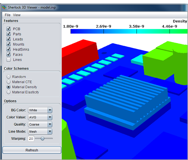
There are no specific analysis results generated by Sherlock for heat sinks. Much like mount points and mechanical parts, they are used to make the FEA model itself more accurate, thereby affecting all PCB and component results. Nonetheless, heat sink can be selectively viewed in the Sherlock 3D Viewer as part of the FEA model and/or analysis results. For example, the following image shows a heat sink mounted on top of a large component:
Heat sinks may be selectively hidden and displayed in the 3D Viewer by enabling or disabling Heat Sinks in the Features panel.
Note: In the 3D Viewer, when viewing any of the color schemes related to material properties (Material CTE, Material Conductivity, Material Density, and Material Elasticity), the values represented are for the material at 20°C only.