


Optimization Operands (Alphabetically)
This section provides a detailed description of each operand, listed alphabetically in a single table.
| NAME | Description |
| ABCD | The ABCD values used by the grid distortion feature to compute generalized distortion. See "Grid Distortion". The reference field number is defined by Ref Fld. The wavelength number is defined by Wave. Data is 0 for A, 1 for B, 2 for C, and 3 for D. See also "DISA". |
| ABGT | Absolute value of operand greater than. This is used to make the absolute value of the operand defined by Op# greater than the target value. |
| ABLT | Absolute value of operand less than. This is used to make the absolute value of the operand defined by Op# less than the target value. |
| ABSO | Absolute value of the operand defined by Op#. |
| ACOS | Arc cosine of the value of the operand defined by Op#. If Flag is 0, then the units are radians, otherwise, degrees. |
| AMAG | Angular magnification. This is the ratio of the image to object space paraxial chief ray angles at the wavelength defined by Wave. Not valid for non-paraxial systems. |
| ANAC | Angular aberration radial direction measured in image space with respect to the centroid at the wavelength defined by Wave. This quantity is defined as: ε = SQRT[(l-lc)2 + (m-mc)2]where l and m are the x and y direction cosines of the ray and the c subscript indicates the centroid. See "Hx, Hy, Px, and Py". |
| ANAR | Angular aberration radius measured in image space at the wavelength defined by Wave with respect to the primary wavelength chief ray. This quantity is defined as: ε = SQRT[(l-lc)2 + (m-mc)2]where l and m are the x and y direction cosines of the ray and the c subscript indicates the chief ray. See"Hx, Hy, Px, and Py". |
| ANAX | Angular aberration x direction measured in image space at the wavelength defined by Wave with respect to the primary wavelength chief ray. This quantity is defined as:ε = l-lcwhere l is the x direction cosine of the ray and the c subscript indicates the chief ray. See "Hx, Hy, Px, and Py". |
| ANAY | Angular aberration y direction measured in image space at the wavelength defined by Wave with respect to the primary wavelength chief ray. This quantity is defined as:ε = m-mc where m is the y direction cosine of the ray and the c subscript indicates the chief ray. See "Hx, Hy, Px, and Py". |
| ANCX | Angular aberration x direction measured in image space at the wavelength defined by Wave with respect to the centroid. This quantity is defined as:ε = l-lcwhere l is the x direction cosine of the ray and the c subscript indicates the centroid. ANCX has the same restrictions that TRAC does; see TRAC for a detailed discussion. See "Hx, Hy, Px, and Py" in Modifying the merit function. |
| ANCY | Angular aberration y direction measured in image space at the wavelength defined by Wave with respect to the centroid. This quantity is defined as:ε = m-mc where m is the y direction cosine of the ray and the c subscript indicates the centroid. ANCY has the same restrictions that TRAC does; see TRAC for a detailed discussion. See "Hx, Hy, Px, and Py" in Modifying the merit function. |
| ASIN | Arcsine of the value of the operand defined by Op#. If Flag is 0, then the units are radians, otherwise, degrees. |
| ASTI | Astigmatism in waves contributed by the surface defined by Surf at the wavelength defined by Wave. If Surf is zero, the sum for the entire system is used. This is the third order astigmatism calculated from the Seidel coefficients, and is not valid for non-paraxial systems. |
| ATAN | Arctangent of the value of the operand defined by Op#. If Flag is 0, then the units are radians, otherwise, degrees. |
| AXCL | Axial color, measured in lens units for focal systems and diopters for afocal systems. This is the image separation between the two wavelengths defined by Wave1 and Wave2. If Zone is zero, paraxial rays are used to determine the paraxial image locations. If Zone is greater than 0.0 and less than or equal to 1.0, real marginal rays are used to determine the image locations. In this case, Zone corresponds to the Py coordinate of the real marginal ray.See "Hx, Hy, Px, and Py". |
| BFSD | Best Fit Sphere (BFS) data. For a complete description, see "Sag Table". BFSD uses the Minimum Volume criterion. The data is computed for the surface defined by Surf. The value returned depends upon the value of Data as follows:0 - BFS curvature in inverse lens units1 - BFS radius of curvature in lens units2 - Vertex offset from BFS in lens units3 - Maximum depth of material to remove in lens units4 - Total volume of material to use in cubic lens units5 - The maximum slope (dz/dr) difference between the surface and BFS (dimensionless)6 - RMS of the depth of material to remove in lens units7 - RMS of the slope (dz/dr) difference between the surface and BFS (dimensionless)The MinR and MaxR are the minimum and maximum radial coordinate over which the BFS data is computed. If both values are zero, the minimum radial coordinate used is zero and the maximum radial coordinate used is the clear semi-diameter or semi-diameter of the surface. |
| BIOC | Biocular Convergence. Returns the convergence between two eye configurations in milliradians. The left and right eye configurations are specified using the Left and Right values. The other parameters are:Wave: The wavelength number to use.UseCos: If 0 field units are degrees, otherwise field is in direction cosine units.Xang/Yang: The X and Y angle or cosines at which to compute the convergence.If the chief rays from both configurations at the specified angles do not pass through to the image without vignetting, an error is reported. See "Divergence/Convergence" for more information and important assumptions. |
| BIOD | Biocular Dipvergence. Returns the dipvergence between two eye configurations in milliradians. See BIOC above for details. |
| BIPF | Unused. |
| BLNK | Does nothing. Used for separating portions of the operand list. A comment line may optionally be typed in the space to the right of the operand name; this comment will be displayed in the editor as well as in the merit function listing. |
| BLTH | Blank thickness. Computes the minimum thickness of the glass blank required to create the volume following the surface defined by Surf. The sag of the surface and the one following are computed at 200 radial points along axes defined by the Code value. Use Code = 0 for +Y axis, 1 for +X axis, 2 for -Y axis, 3 for -X axis, and 4 for all four axes. This operand has a mode flag. Mode = 0 (default) to use Mech Semi-Dia and Mode = 1 to use Clear Semi-Dia value displayed on the Lens Data Editor. |
| BSER | Boresight error. Boresight error is defined as the radial chief ray coordinate traced for the on axis field and wavelength defined by Wave divided by the effective focal length. This definition yields a measure of the angular deviation of the image. |
| CARD |
Cardinal Point data. This operand will return the location of the 6 cardinal points for object space and 6 cardinal points for image space, including principal, anti-principal, nodal, anti-nodal and focal planes, in Lens units. The calculation is performed for any defined wavelength and either the X-Z or Y-Z plane orientations. Object space positions are measured with respect to the surface defined as Surf1, and the image space positions are measured with respect to the surface defined as Surf2. The index in both the object space and image space is considered. Surf1: The starting surface number of the group to compute the cardinal points for. Surf2: The ending surface number of the group to compute the cardinal points for. Wave: The wavelength number to use for the computation. Orientation: The orientation to use for computing the cardinal plane locations (0 – YZ plane or 1 – XZ plane). The value returned depends upon the value of Data as follows: 0 – Object Space Focal Length 1 – Image Space Focal Length 2 – Object Space Focal Plane 3 – Image Space Focal Plane 4 – Object Space Principal Plane 5 – Image Space Principal Plane 6 – Object Space Anti-Principal Plane 7 – Image Space Anti-Principal Plane 8 – Object Space Nodal Plane 9 – Image Space Nodal Plane 10 – Object Space Anti-Nodal Plane 11 – Image Space Anti-Nodal Plane |
| CEGT | Boundary operand that constrains the coating extinction offset of the coating layer defined by Layr for the surface defined by Surf to be greater than the target value. Use Surf = 0 for all surfaces, Layr = 0 for all layers. |
| CELT | Boundary operand that constrains the coating extinction offset of the coating layer defined by Layr for the surface defined by Surf to be less than the target value. Use Surf = 0 for all surfaces, Layr = 0 for all layers. |
| CEHX | Huygens PSF centroid X position. This operand uses the Huygens PSF to determine the x coordinate of the centroid for any field point. The centroid accounts for all apodization and apertures, and optionally polarization. The parameters for this operand are:Wave: The wavelength number to use (0 for polychromatic, otherwise use the monochromatic wavelength number).Field: The integer field number to use.Pol?: Set to 0 to ignore polarization and 1 to consider it.Pupil Samp: Use 1 for 32x32, 2 for 64x64, etc.Image Samp: Use 1 for 32x32, 2 for 64x64, etc.All Conf?: Set to 0 to use the current configuration (defined by the last CONF operand preceding this operand), and 1 to sum over all configurations. See Huygens PSF for a full discussion of this option.This feature always uses the default image delta. The evaluation surface is always the image surface (see IMSF). When CEHX is followed by a CEHY with identical settings, both are computed with the same ray set to save time.See also CENX, CENY, CNPX, CNPY, CNAX, and CNAY. |
| CEHY | Huygens PSF centroid Y position. See CEHX. |
| CENX | Centroid X position. This operand uses a grid of rays to determine the x coordinate of the centroid of all rays from a single field point. The centroid accounts for apodization and apertures, and optionally polarization. The parameters for this operand are:Surf: The surface number to use (use 0 for the image surface).Wave: The wavelength number to use (0 for polychromatic, otherwise use the monochromatic wavelength number).Field: The integer field number to use.Pol?: Set to 0 to ignore polarization and 1 to consider it.Samp: The grid size. A value of 10 would yield a 10 x 10 grid of rays.When CENX is followed by a CENY with identical settings, both are computed with the same ray set to save time. |
| CENY | Centroid Y position. See CENX. |
| CEVA | Boundary operand that constrains the coating extinction offset of the coating layer defined by Layr for the surface defined by Surf to be equal to the target value. |
| CIGT | Boundary operand that constrains the coating index offset of the coating layer defined by Layr for the surface defined by Surf to be greater than the target value. Use Surf = 0 for all surfaces, Layr = 0 for all layers. |
| CILT | Boundary operand that constrains the coating index offset of the coating layer defined by Layr for the surface defined by Surf to be less than the target value. Use Surf = 0 for all surfaces, Layr = 0 for all layers. |
| CIVA | Boundary operand that constrains the coating index offset of the coating layer defined by Layr for the surface defined by Surf to be equal to the target value. |
| CMFV | Construction merit function value. This operand calls the merit functions defined in either of the two construction systems used to define an optically fabricated hologram. The Cons# is either 1 or 2, for the first or second construction system, respectively. The Op# is either 0, which will return the entire merit function value from the construction system; or it is an integer which defines the operand row # from which to extract the value from. For example, if Cons# is 2 and Op# is 7, CMFV will return the value of merit function operand 7 in construction file 2.If there are more than one optically fabricated hologram surfaces in the playback system being optimized, the Cons# may be incremented by 2 to specify the second surface parameters be used, or by 4 to indicate the third hologram surface construction optics be used, and so on. For example, a Cons# of 7 would indicate construction system 1 on the fourth optically fabricated hologram surface present. |
| CMGT | Boundary operand that constrains the coating multiplier of the coating layer defined by Layr for the surface defined by Surf to be greater than the target value. Use Surf = 0 for all surfaces, Layr = 0 for all layers. |
| CMLT | Boundary operand that constrains the coating multiplier of the coating layer defined by Layr for the surface defined by Surf to be less than the target value. Use Surf = 0 for all surfaces, Layr = 0 for all layers. |
| CMVA | Boundary operand that constrains the coating multiplier of the coating layer defined by Layr for the surface defined by Surf to be equal to the target value. |
| CNAX | Centroid angular x direction. This operand computes the X angle in radians relative to the local Z axis of the centroid of rays from any field point. The centroid accounts for apodization and apertures, and optionally polarization.Surf: The surface number to use (use 0 for the image surface).Wave: The wavelength number to use (0 for polychromatic, otherwise use the monochromatic wavelength number).Hx/Hy: See normalized field coordinates to use.Pol?: Set to 0 to ignore polarization and 1 to consider it.Samp: The grid size. A value of 10 would yield a 10 x 10 grid of rays.When CNAX is followed by a CNAY with identical settings, both are computed with the same ray set to save time.See also CNAY, CNPX, CNPY, CENX, CENY, CEHX, CEHY. |
| CNAY | Centroid angular y direction. See CNAX. |
| CNPX | Similar to CNAX, but computes the centroid position rather than angle. |
| CNPY | Similar to CNAY, but computes the centroid position rather than angle. |
| CODA | Coating Data. This feature traces a polarized ray using the system global polarization state (see "Polarization"). Even if the global polarization state is set to "unpolarized", the defined polarization state is used because the data computed by CODA is polarization state specific.The polarized ray may be traced from any field point in object space defined by Field to any point in the pupil, to the surface defined by Surf. If Surf is zero, the ray is traced to the image surface. The wavelength is defined by Wave while Px and Py define the normalized pupil coordinate. The absolute value of Data determines what data is returned as follows:0: The relative transmitted polarized intensity (see 8)1, 2, 3: The intensity reflectance R, transmittance T, absorption A4,5: The field amplitude transmittance real, imaginary6,7: The field amplitude reflectance real, imaginary8: The relative transmitted unpolarized intensity (see 0)101, 102: E field out X real, imaginary103, 104: E field out Y real, imaginary105, 106: E field out Z real, imaginary110: The phase difference between Ex and Ey; Pxy111, 112, 113: The E field phase Px, Py, Pz121, 122, 123: The major axis, minor axis, and angle in degrees of the polarization ellipseIf the data is related to the coating (1-7), and Data is negative, the data is for the "S" polarization, otherwise the data is for the "P" polarization.See "Hx, Hy, Px, and Py". |
| COGT | Boundary operand that constrains the conic of the surface defined by Surf to be greater than the specified target value. |
| COLT | Boundary operand that constrains the conic of the surface defined by Surf to be less than the specified target value. |
| COMA | Coma in waves contributed by the surface defined by Surf at the wavelength defined by Wave. If Surf is zero, the sum for the entire system is used. This is the third order coma calculated from the Seidel coefficients, and is not valid for non-paraxial systems. |
| CONF | Configuration. This operand is used to change the configuration number to the configuration defined by Cfg# during merit function evaluation. This permits optimization across multiple configurations with a single merit function. This operand does not use the target or weight columns. |
| CONS | Constant value. This is used to enter in constant values for use in other operand computations. The value will be identical to the target value. |
| COSA | Unused. |
| COSI | Cosine of the value of the operand defined by Op#. If Flag is 0, then the units are radians, otherwise, degrees. |
| COVA | Conic value. Returns the conic constant of the surface defined by Surf. |
| CTGT | Center thickness greater than. This boundary operand constrains the center thickness of the surface defined by Surf to be greater than the specified target value. See also MNCT. |
| CTLT | Center thickness less than. This boundary operand constrains the center thickness of the surface defined by Surf to be less than the specified target value. See also MXCT. |
| CTVA | Center thickness value. Constrains the center thickness of the surface defined by Surf to be equal to the specified target value. |
| CVGT | Curvature greater than. This boundary operand constrains the curvature of the surface defined by Surf to be greater than the target value. |
| CVIG | Clears the vignetting factors. This operand clears the current vignetting factors for the remainder of the operands in the current configuration. See also "SVIG". |
| CVLT | Curvature less than. This boundary operand constrains the curvature of the surface defined by Surf to be less than the target value. |
| CVOL | Cylinder volume. This operand computes the volume in cubic lens units of the smallest cylinder that will contain the range of surfaces defined by Surf1 and Surf2. Only the vertex positions and semi- diameters are used in the calculation, not the sag. This operand has a mode flag. Mode = 0 (default) to use Mech Semi-Dia and Mode = 1 to use Clear Semi-Dia value displayed on the Lens Data Editor. The range of surfaces should not include any coordinate breaks. |
| CVVA | Curvature value. This operand constrains the curvature of the surface defined by Surf to be equal to the specified target value. |
| DCRV (Data input) |
The curvature data in lens units of the surface defined by Surf. Curvature data includes the Mean, PV, Minimum, or Maximum curvature value across a specified surface as well as the X or Y coordinates of Min curvature value, or the X or Y coordinates of the Max curvature value. This operand has data, sampling, off-axis, remove, best-fit sphere (BFS), and Orientation flags. The options for the Data input will be: 1 – RMS curvature value over the surface. 2 – PV curvature value over the surface. 3 – Minimum curvature value over the surface. 4 – Maximum curvature value over the surface. 5 – X coordinate for the point on the surface with the minimum curvature value. 6 – Y coordinate for the point on the surface with the minimum curvature value. 7 – X coordinate for the point on the surface with the maximum curvature value. 8 – Y coordinate for the point on the surface with the maximum curvature value. 9 – ROC of the best-fit sphere 10 – Z Offset of the best-fit sphere vertex from the local coordinate system 11 – X decenter of off-axis coordinate system from the surface's local coordinate system 12 – Y decenter of off-axis coordinate system from the surface's local coordinate system 13 – Z decenter of off-axis coordinate system from the surface's local coordinate system 14 – Tilt about X (a) of off-axis coordinate system, from the surface's local coordinate system 15 – Tilt about Y (b) of off-axis coordinate system, from the surface's local coordinate system 16 – Tilt about Z (g) of off-axis coordinate system, from the surface's local coordinate system
|
| DCRV (Samp input) |
The options for the Samp input will be: 1 – 33 x 33 (default) 2 – 65 x 65 3 – 129 x 129 4 – 257 x 257 5 – 513 x 513 6 – 1025 x 1025 7 – 2049 x 2049 8 – 4097 x 4097 9 – 8193 x 8193 10 – 16385 x 16385
|
| DENC | Diffraction Encircled Energy (distance). This operand computes the distance to the fraction of diffraction encircled, ensquared, x only, or y only (enslitted) energy defined by Frac. For focal mode, the units are micrometers. For afocal mode, the units are afocal mode units. The other parameters are:Samp: The pupil sampling, where 1 yields 32 x 32, 2 yields 64 x 64 etc.Wave: The wavelength number to use (use 0 for polychromatic).Field: The field number.Type: 1 for encircled, 2 for x only, 3 for y only, and 4 for ensquared.Refp: The reference point/algorithm to use. For FFT encircled energy, use Refp = 0 for chief ray, 1 for centroid, and 2 for vertex. For Huygens encircled energy, use Refp = 3 for chief ray, 4 for centroid, and 5 for vertex. When using the Huygens method, I Samp refers to the Huygens image sampling (1 for 32 x 32, 2 for 64 x 64, etc.) and I Delta refers to the Huygens image delta. For a detailed description of the Huygens image sampling and image delta, see "Encircled Energy".If the sampling is too low, the radius returned is 1e+10. See also DENF, GENC and XENC. |
| DENF | Diffraction Encircled Energy (fraction). This operand computes the fraction of diffraction encircled, ensquared, x only, or y only (enslitted) energy at a given distance from the reference point defined by Dist. For focal mode, the distance units are micrometers. For afocal mode, the distance units are afocal mode units.The options and settings are identical to DENC, except Dist, which here is used as the distance at which the fraction of energy is desired. See also DENC, GENC, GENF, and XENC.If the Dist value defined is beyond the point where the encircled energy is very close to 100%, the fraction returned is 1e+10; this is done for optimization efficiency. |
| DIFF | Difference of two operands (Op#1 - Op#2). |
| DIMX |
Distortion maximum. This specifies an upper bound for the absolute value of the distortion. DIMX is based on the same calculation as DISG, and is not related to the Seidel-based calculations given by DIST. Field can be zero, which specifies that the maximum field coordinate be used, or any valid field number. Note the maximum distortion does not always occur at the maximum field coordinate. DIMX only traces chief rays (Px = Py = 0), and thus Px and Py are not user-defined. The reference field is always an on-axis field point (Hx = Hy = 0), even if such a field point has not been defined in the optical system. See DISG for more information. The distortion is calculated at the wavelength defined by Wave. If Absolute is 0, the value returned is in units of percentage. If Absolute is 1, the distortion is given as an absolute length rather than a percentage. This operand may not be valid for non-rotationally symmetric systems. |
| If Absolute is 0, the value returned is in units of percentage. If Absolute is 1, the distortion is given as an absolute length rather than a percentage. | |
| This operand may not be valid for non-rotationally symmetric systems. | |
| DISA | Distortion, ABCD. This operand computes the Radial, X, or Y direction distortion relative to the reference field (Ref Fld), for the chief ray at the wavelength defined by Wave. Data is 0 for radial distortion, 1 for X direction distortion, and 2 for Y direction distortion. The distortion is computed for the chief ray at the field point defined by Field. The A, B, C, D values are user defined. The distortion is computed in the same manner as the grid distortion feature (see "Grid Distortion"). The key difference between this operand and DISG is that the ABCD values are user defined. See also "ABCD" and "DISG". |
| DISC | Distortion, calibrated. This operand computes the calibrated f-theta distortion across the y-field of view at the wavelength defined by Wave, and returns the absolute value of the maximum deviation from linearity of the f-theta condition. |
| If Absolute is 0, the value returned is in units of percentage. If Absolute is 1, the distortion is given as an absolute length (for focal systems) or an absolute deviation in cosine space (for afocal systems) rather than a percentage. This operand is useful for designing f-theta lenses. | |
| DISG |
Generalized distortion, either in percent or as an absolute distance. This operand computes the distortion for any ray in the pupil, from anywhere in the field, at the wavelength defined by Wave, using the field point defined by Field as a reference. The method used and assumptions made for DISG calculations are common to all operands that calculate distortion. DISG cannot be calculated if the field units are angles and the maximum angle equals or exceeds 90 degrees. DISG assumes the predicted magnification is not symmetric. If the field is defined in terms of angles, the normalized field coordinates Hx and Hy are defined as: H=θ/θM where θ is the absolute angle measured from the central on-axis field, and θM is the maximum field angle (see "Maximum field"). If Wave is a positive number, DISG returns the distortion as a percentage. If Wave is a negative number, the absolute value of Wave is used to define the wavelength and the returned value is in units of absolute length rather than percentage.As with all distortion concepts, the best way to avoid confusion and misleading results is to use finite object distances and object heights to define fields rather than field angles.See "Hx, Hy, Px, and Py". |
| DIST | Distortion in waves contributed by the surface defined by Surf at the wavelength defined by Wave. This is the third order distortion calculated from the Seidel coefficients (see "Seidel Coefficients"), and is not valid for non-paraxial systems.If Surf is zero, the distortion is given in percent instead (see "Field Curvature/Distortion" for a detailed definition).If Absolute is set to 1, and the surface number is zero, the distortion is given as an absolute length rather than a percentage. See also DISG. |
| DIVB | Divides the value of any prior operand defined by Op# by any factor defined by Factor. |
| DIVI | Division of first by second operand (Op#1 / Op#2). See also "RECI". |
| DLTN | Delta N. Computes the difference between the maximum and minimum index of refraction on axis for a gradient index surface defined by Surf. The wavelength used is defined by Wave. The minimum and maximum z coordinates used are computed by accounting for the sag of both ends of the surface. See the section "Using gradient index operands". |
| DMFS | Default merit function start. This operand is a flag to indicate where the default merit function should be appended, if one is subsequently created. The row number after this operand will appear as the default "Start At" row on the default merit function dialog box. |
| DMGT | Diameter greater than. This boundary operand constrains the diameter of the surface defined by Surf to be greater than the specified target value. This operand has a mode flag. Mode = 0 (default) to use Mech Semi-Dia and Mode = 1 to use Clear Semi-Dia value displayed on the Lens Data Editor. The diameter is simply two times the value of the selected semi-diameter |
| DMLT | Diameter less than. This boundary operand constrains the diameter of the surface defined by Surf to be less than the specified target value. This operand has a mode flag. Mode = 0 (default) to use Mech Semi-Dia and Mode = 1 to use Clear Semi-Dia value displayed on the Lens Data Editor. The diameter is simply two times the value of the selected semi-diameter. |
| DMVA | Diameter value. This operand constrains the diameter of the surface defined by Surf to be equal to the specified target value. This operand has a mode flag. Mode = 0 (default) to use Mech Semi-Dia and Mode = 1 to use Clear Semi-Dia value displayed on the Lens Data Editor. The diameter is simply two times the value of the selected semi-diameter. |
| DPHS |
The phase data in waves at the primary system wavelength of the surface defined by Surf. Phase data includes the RMS, PV, Minimum, or Maximum phase value across a specified surface as well as the X or Y coordinates of Min phase value, or the X or Y coordinates of the Max phase value. This operand has data, sampling, and remove flags. The options for the Data input will be: 1 – RMS phase value over the surface. 2 – PV phase value over the surface. 3 – Minimum phase value over the surface. 4 – Maximum phase value over the surface. 5 – X coordinate for the point on the surface with the minimum phase value. 6 – Y coordinate for the point on the surface with the minimum phase value. 7 – X coordinate for the point on the surface with the maximum phase value. 8 – Y coordinate for the point on the surface with the maximum phase value. 9 – Value of the constant phase removed from the data. 10 – Value of the tilt about X removed from the data. 11 – Value of the tilt about Y removed from the data. 12 – Value of the power removed from the data. The options for the Samp input will be: 1 – 33 x 33 (default) 2 – 65 x 65 3 – 129 x 129 4 – 257 x 257 5 – 513 x 513 6 – 1025 x 1025 7 – 2049 x 2049 8 – 4097 x 4097 9 – 8193 x 8193 10 – 16385 x 16385
|
| DSAG (Data input) |
The sag data in lens units of the surface defined by Surf. Sag data includes the RMS, PV, Minimum, or Maximum sag value across the specified surface as well as the X or Y coordinates of Min sag value, or the X or Y coordinates of the Max sag value. This operand has data, sampling, off-axis, remove, and best-fit sphere (BFS) flags. The options for the Data input will be: 1 – RMS sag value over the surface (default). 2 – PV sag value over the surface. 3 – Minimum sag value over the surface. 4 – Maximum sag value over the surface. 5 – X coordinate for the point on the surface with the minimum sag value. 6 – Y coordinate for the point on the surface with the minimum sag value. 7 – X coordinate for the point on the surface with the maximum sag value. 8 – Y coordinate for the point on the surface with the maximum sag value. 9 – Radius of curvature of the best-fit sphere. 10 – Z Offset of the best-fit sphere vertex from the local coordinate system. 11 – X decenter of off-axis coordinate system from the surface's local coordinate system. 12 – Y decenter of off-axis coordinate system from the surface's local coordinate system. 13 – Z decenter of off-axis coordinate system from the surface's local coordinate system. 14 – Tilt about X (a) of off-axis coordinate system, from the surface's local coordinate system. 15 – Tilt about Y (b) of off-axis coordinate system, from the surface's local coordinate system. 16 – Tilt about Z (g) of off-axis coordinate system, from the surface's local coordinate system. |
| DSAG (Samp input) |
The options for the Samp input will be: 1 – 33 x 33 (default) 2 – 65 x 65 3 – 129 x 129 4 – 257 x 257 5 – 513 x 513 6 – 1025 x 1025 7 – 2049 x 2049 8 – 4097 x 4097 9 – 8193 x 8193 10 – 16385 x 16385
|
| DSLP (Data input) |
The slope data in lens units of the surface defined by Surf. Slope data includes the Mean, PV, Minimum, or Maximum slope value across a specified surface as well as the X or Y coordinates of Min slope value, or the X or Y coordinates of the Max slope value. This operand has data, sampling, off-axis, remove, best-fit sphere (BFS), and Orientation flags. The options for the Data input will be: 1 – RMS slope value over the surface (default). 2 – PV slope value over the surface. 3 – Minimum slope value over the surface. 4 – Maximum slope value over the surface. 5 – X coordinate for the point on the surface with the minimum slope value. 6 – Y coordinate for the point on the surface with the minimum slope value. 7 – X coordinate for the point on the surface with the maximum slope value. 8 – Y coordinate for the point on the surface with the maximum slope value. 9 – ROC of the best-fit sphere. 10 – Z Offset of the best-fit sphere vertex from the local coordinate system. 11 – X decenter of off-axis coordinate system from the surface's local coordinate system. 12 – Y decenter of off-axis coordinate system from the surface's local coordinate system. 13 – Z decenter of off-axis coordinate system from the surface's local coordinate system. 14 – Tilt about X (a) of off-axis coordinate system, from the surface's local coordinate system. 15 – Tilt about Y (b) of off-axis coordinate system, from the surface's local coordinate system. 16 – Tilt about Z (g) of off-axis coordinate system, from the surface's local coordinate system.
|
| DSLP (Samp input) |
The options for the Samp input will be: 1 – 33 x 33 (default) 2 – 65 x 65 3 – 129 x 129 4 – 257 x 257 5 – 513 x 513 6 – 1025 x 1025 7 – 2049 x 2049 8 – 4097 x 4097 9 – 8193 x 8193 10 – 16385 x 16385
|
| DXDX | Derivative of transverse x-aberration with respect to x-pupil coordinate. This is the slope of the ray fan plot at the specified pupil coordinate at the wavelength defined by Wave. See "Hx, Hy, Px, and Py". |
| DXDY | Derivative of transverse x-aberration with respect to y-pupil coordinate. This is the slope of the ray fan plot at the specified pupil coordinate at the wavelength defined by Wave. See "Hx, Hy, Px, and Py". |
| DYDX | Derivative of transverse y-aberration with respect to x-pupil coordinate. This is the slope of the ray fan plot at the specified pupil coordinate at the wavelength defined by Wave. See "Hx, Hy, Px, and Py". |
| DYDY | Derivative of transverse y-aberration with respect to y-pupil coordinate. This is the slope of the ray fan plot at the specified pupil coordinate at the wavelength defined by Wave. See "Hx, Hy, Px, and Py". |
| EFFL | Effective focal length in lens units. The wavelength used is defined by Wave. This is paraxial, and may not be accurate for non-paraxial systems. |
| EFLA | Effective focal length in air in lens units. This is calculated from the surface defined by Surf to the next. The wavelength used is defined by Wave. |
| EFLX | Effective focal length in the local x plane of the range of surfaces defined by Surf1 and Surf2 at the primary wavelength. |
| EFLY | Effective focal length in the local y plane of the range of surfaces defined by Surf1 and Surf2 at the primary wavelength. |
| EFNO | Effective F/#. This operand computes the Effective F/# of the field point defined by Field. For a discussion of Effective F/# see "Effective F/#". The other parameters are:Samp: The grid size. A value of 10 would yield a 10 x 10 grid of rays.Wave: The wavelength number to use.Pol?: Set to 0 to ignore polarization and 1 to consider it. See also RELI. |
| ENDX | End execution. Terminates the computation of the merit function. All remaining operands are ignored. |
| ENPP | Entrance pupil position in lens units, with respect to the first surface. This is the paraxial pupil position, valid only for centered systems. |
| EPDI | Entrance pupil diameter in lens units. |
| ERFP | Edge Response Function Position. This operand computes the x or y position of the point at which the edge response function reaches a certain relative value. For details on the edge response function calculation, see "Geometric Line/Edge Spread". The Sampling value is 1 for32x32, 2 for 64x64, etc. Wave is the wavelength number or 0 for polychromatic. Field is the field number. Type determines that data to be returned. If Type is 0 or 1, the x position (for edges parallel to the local y axis) or y position (for edges parallel to the local x axis) relative to the chief ray in lens units is returned. If Wave is zero, the primary wavelength chief ray is the reference point. If Type is 2 or 3, the x or y position in lens units relative to the surface vertex is returned. Fraction is the relative value of the edge response curve, and must be between 0.01 and 0.99. Max Radius is the maximum radial size of the integration window in micrometers. If Max Radius is zero a default value is used, and this is the recommended setting in most cases.Note that the edge response function is normally defined with the "bright" side of the edge being on the + side of the integration coordinate, which means the edge response goes to 1 as the coordinate becomes more positive. To compute results for the reversed edge orientation, with the bright side on the negative side of the coordinate, use the value (1-fraction) instead of (fraction). For example, to get the 80% response coordinate for a reversed edge, use Fraction = 0.20.If afocal mode is used, all returned values are in afocal analysis units. |
| EQUA | Equal operand. This operand constrains all operands within the range of operands defined by Op#1 and Op#2 to have the same value within the tolerance specified by the target. The value of this operand is computed by finding the average of the range of values, and then summing the absolute value of the errors between each operand and the average if the error exceeds the target value. See SUMM and OSUM. |
| ETGT | Edge thickness greater than. This boundary operand constrains the edge thickness of the surface defined by Surf to be greater than the specified target value. The edge thickness is calculated along the +y axis if Code is zero, the +x axis if Code is 1, the -y axis if Code is 2, and the -x axis if Code is 3. This operand has a mode flag. Mode = 0 (default) to use Mech Semi-Dia and Mode = 1 to use Clear Semi-Dia value displayed on the Lens Data Editor. See also MNET. |
| ETLT | Edge thickness less than. This boundary operand constrains the edge thickness of the surface defined by Surf to be less than the specified target value. The edge thickness is calculated along the +y axis if Code is zero, the +x axis if Code is 1, the -y axis if Code is 2, and the -x axis if Code is 3. This operand has a mode flag. Mode = 0 (default) to use Mech Semi-Dia and Mode = 1 to use Clear Semi-Dia value displayed on the Lens Data Editor. See also MXET. |
| ETVA | Edge thickness value. Constrains the edge thickness of the surface defined by Surf to be equal to the specified target value. The edge thickness is calculated along the +y axis if Code is zero, the +x axis if Code is 1, the -y axis if Code is 2, and the -x axis if Code is 3. This operand has a mode flag. Mode = 0 (default) to use Mech Semi-Dia and Mode = 1 to use Clear Semi-Dia value displayed on the Lens Data Editor. See also MNET. |
| EXPD | Exit pupil diameter in lens units. This is the paraxial pupil diameter, valid only for centered systems. |
| EXPP | Exit pupil position in lens units, with respect to the image surface. This is the paraxial pupil position, valid only for centered systems. |
| FCGS | Generalized field curvature, sagittal. The field curvature value for any field point, at the wavelength defined by Wave. The value is generalized to return reasonable results even for non-rotationally symmetric systems; see "Field Curvature/Distortion. See "Hx, Hy, Px, and Py". |
| FCGT | Generalized field curvature, tangential; see FCGS. |
| FCUR | Field curvature in waves contributed by the surface defined by Surf at the wavelength defined by Wave. If Surf is zero, the sum for the entire system is used. This is the third order field curvature calculated from the Seidel coefficients, and is not valid for non-paraxial systems. |
| FDMO | Field Data Modify. This operand allows temporary modification of field position data. The operand allows new field coordinates and vignetting factors (except for tangential angle, which cannot be modified by this operand) for any field coordinate. All subsequent operands will use the modified field data. The original field data is restored when a FDRE operand is reached with the same field number argument, or a CONF operand is reached (regardless of the configuration number referenced by the CONF operand), or after the last operand in the merit function is reached.Field: The field number to modify.Hx, Hy: The normalized field coordinates for the new field position.VDX, VDY, VCX, VCY: The vignetting factor data for the new field position. See " Vignetting factors ". |
| FDRE | Field Data Restore. See FDMO. Field: The field number to restore. |
| FICL |
Fiber coupling efficiency for single mode fibers. The calculated value is the total coupled energy efficiency, relative to unity. The parameters of this operand are: Samp: The pupil sampling, where 1 yields 32 x 32, 2 yields 64 x 64 etc. Wave: The wavelength number to use. Field: The integer field position number. IgSrc: If this parameter is zero, then the object source fiber is considered; otherwise, the object source fiber is ignored. Sna: The source fiber NA. Rna: The receiver fiber NA.
Data: This controls what data is returned as well as the algorithm to use.
|
|
Note: The operand parameters can overwrite the settings from the CFG file. See the following table for detailed behavior when Data is 6~11:
|
|
|
Pol?: Set to 0 to ignore polarization and 1 to consider it. See "Fiber Coupling Efficiency" for details. See also FICP. |
|
| FICP |
Fiber coupling as computed using the Physical Optics Propagation (POP) algorithm, using whatever the current default settings are for the POP feature. Surf: This controls the end surface used in the POP calculation. If Surf is zero, then the saved ending surface number will be used; otherwise, the specified surface will be used as the ending surface. Wave: This controls the wavelength used in the POP calculation. If Wave is zero, then the saved wavelength number will be used; otherwise, the specified wavelength number will be used. Data: This controls what data is returned. If Data is 0 the total power coupling is returned. If Data is 1, the amplitude coupling for the Ex field is returned. If Data is 2 or 3, the real or imaginary part of the amplitude coupling for the Ex field is returned, respectively. If Data is 4, the amplitude coupling for the Ey field is returned. If Data is 5 or 6, the real or imaginary part of the amplitude coupling for the Ey field is returned, respectively. If the beam is unpolarized the Ey values wil be zero. Data inputs 1-6 request a polarized POP calculation, but if the input beam is unpolarized, the field coupling efficiency amplitudes and phases are not physically well-defined. Therefore, values of 0.0 will be returned if the input beam is unpolarized. To use this operand, first define the settings on the POP analysis feature as desired, then press Save on the settings box. The operand FICP will return the same efficiency as computed by the POP feature. Field: This controls the field number used in the POP calculation. If Field is zero, then the saved field number will be used; otherwise, the specified field number will be used. This operand is redundant with the more general POPD. See " Computing Fiber Coupling ". See also FICL. |
| FOUC | Foucault analysis. This operand returns the RMS difference between the computed and reference shadowgram as computed by the Foucault analysis feature, using whatever the current default settings are. To use this operand, first define the settings on the Foucault analysis feature as desired, then press Save on the settings box. The operand FOUC will return the RMS difference between the computed and reference shadowgrams, regardless of how the "data" option is set in the saved configuration file. Using this operand, the optical system wavefront aberrations may be optimized to produce the reference shadowgram. |
| FREZ | Freeform Z object constraints. This operand computes various values from the shape of a Freeform Z object described in "Freeform Z". Surf is the surface number of the NSC group, use 1 for NSC program mode. Object is the object number, which must be a Freeform Z object for thisoperand to compute any data. The Data value determines what value is computed by the operand as follows:1: Maximum z value. Nnote minimum z value is always zero.2: Maximum z increment. This is the biggest difference between adjacent z control points.3: Minimum z increment. This is the smallest difference between adjacent z control points.4: Minimum y value. This value is for the entire length of the solid, not just at control points.5: Maximum y value. This value is for the entire length of the solid, not just at control points.6: Maximum y increment. This is the biggest difference between adjacent y control points.7: Minimum y increment. This is the smallest difference between adjacent y control points.8: Volume of the object in lens units cubed.9: Monotonic deviation. This is the largest change in adjacent y values whose sign deviates from the sign of the first y change going from 0 to positive z coordinates.10: Minimum slope.11: Maximum slope.Once the Data has been computed, the Mode value determines how the operand behaves. If Mode is 1, the FREZ operand returns the data. If Mode is 2, the operand returns the data value only if the data value is less than the target value, otherwise the target value is returned. This mode is used to enforce a "greater than" boundary on the data. If Mode is 3, the operand returns the data value only if the data value is greater than the target value, otherwise the target value is returned. This mode is used to enforce a "less than" boundary on the data. |
| FTGT | Full thickness greater than. This boundary operand constrains the full thickness of surface Surf to be greater than the specified target value. The full thickness is computed at 200 points between the vertex and edge along the +y radial direction, including the sag of the surface and the sag of the next surface. This operand has a mode flag. Mode = 0 (default) to use Mech Semi-Dia and Mode = 1 to use Clear Semi-Dia value displayed on the Lens Data Editor. The operand is useful for constraining surfaces which do not have their minimum or maximum thickness at the center or edge, but at some intermediate zone. See FTLT. |
| FTLT | Full thickness less than. See FTGT. |
| GAOI |
Ghost angle of incidence. This operand calculates the angle of incidence of a ray in degrees at any surface after a double-bounce ghost reflection. The Surf1 and Surf2 values define the first and second surface numbers to define the ghost path. Note the first bounce surface number must be larger than the second bounce surface number. The primary wavelength is always used. Surf3 determines the surface at which the angle of incidence is computed and has to be greater than Surf2. When Surf3 is negative, its absolute value directly specifies the surface number in the ghost system. See "Ghost Focus Generator" for more information of ghost systems. By default, the SetVig = 0. When SetVig = 1, vignetting factors are set for the ghost system when calculating the angle of incidence. Note that setting vignetting factors will cause beams to fully pass all surface apertures when possible by shifting and shrinking the beams. See "Vignetting." Note that if Surf2 is a mirror in the original system, the beam cannot reach the image surface in ghost system. Therefore Surf3 can only be 0 or negative. Surf3 = 0 represents the last surface in the ghost system, which is the object surface in the original system. See "Hx, Hy, Px, and Py". |
| GBPD | Gaussian beam (paraxial) divergence in the optical space following the surface defined by Surf at the wavelength defined by Wave. The other parameters are:UseX: If this parameter is non-zero, then the computation is for the x-direction beam, otherwise, it is for the y-direction.W0: The input beam waist size in lens units.S1toW: The distance from Surface 1 to the waist location in lens units. See the Gaussian beam feature for details.M2 Factor: The M Squared value for the beam. See the Gaussian beam feature for details. |
| GBPP | Gaussian beam (paraxial) position, which is the distance from the waist to the surface, in the optical space following the specified surface. See GBPD. |
| GBPR | Gaussian beam (paraxial) radius of curvature in the optical space following the specified surface. See GBPD. |
| GBPS | Gaussian beam (paraxial) size in the optical space following the specified surface. See GBPD. |
| GBPW | Gaussian beam (paraxial) waist in the optical space following the specified surface. See GBPD. |
| GBPZ | Gaussian beam (paraxial) Rayleigh range in the optical space following the specified surface. See GBPD. |
| GBSD | Gaussian beam (skew) divergence in the optical space following the specified surface. The input beam is aligned along the chief ray of the field defined by Field. The other parameters are:In#: The surface number to start the propagation.Out#: The surface at which to compute the Skew Gaussian Beam data.Wave: The wavelength number to use.StoW: The starting surface to waist distance in lens units.W0: The input beam waist size in lens units. If W0 is positive, then the computation is for the y- direction beam, otherwise, it is for the x-direction.For details on the Skew Gaussian Beam feature, see " Skew Gaussian Beam ". |
| GBSP | Gaussian beam (skew) position, which is the distance from the waist to the surface, in the optical space following the specified surface. See GBSD. |
| GBSR | Gaussian beam (skew) radius in the optical space following the specified surface. See GBSD. |
| GBSS | Gaussian beam (skew) size in the optical space following the specified surface. See GBSD. |
| GBSW | Gaussian beam (skew) waist in the optical space following the specified surface. See GBSD. |
| GCOS | Glass cost. This operand returns the relative cost factor as listed in the glass catalog for the glass on the surface defined by Surf. |
| GENC | Geometric Encircled Energy (distance). This operand computes the distance to the fraction of geometric encircled, ensquared, x only, or y only (enslitted) energy defined by Frac. For focal mode, the units are micrometers. For afocal mode, the units are afocal mode units. The other parameters are:Samp: The pupil sampling, where 1 yields 32 x 32, 2 yields 64 x 64 etc.Wave: The wavelength number to use (use 0 for polychromatic).Field: The field number.Type: 1 for encircled, 2 for x only, 3 for y only, and 4 for ensquared.Refp: The reference point to use. Use 0 for chief ray, 1 for centroid, 2 for vertex, and 3 for middle of the spot.No Diff Lim: If 0, the results are scaled by the diffraction limit, otherwise, no accounting of diffraction is done.See also GENF, DENC, DENF, and XENC. |
| GENF | Geometric Encircled Energy (fraction). This operand computes the fraction of geometric encircled, ensquared, x only, or y only (enslitted) energy at a given distance from the reference point defined by Dist. The options and settings are identical to GENC, except Dist, which here is used as the distance at which the fraction of energy is desired. See also GENC, DENC, DENF, and XENC. |
| GLCA | Global x-direction orientation vector component of the surface defined by Surf. |
| GLCB | Global y-direction orientation vector component of the surface defined by Surf. |
| GLCC | Global z-direction orientation vector component of the surface defined by Surf. |
| GLCR | Global Coordinate Rotation Matrix component at the surface defined by Surf. The 3 x 3 R matrix has 9 components. If Data is 1, GLCR returns R[1][1], if Data is 2, GLCR returns R[1][2], etc... through Data = 9 returning R[3][3]. |
| GLCX | Global vertex x-coordinate of the surface defined by Surf. |
| GLCY | Global vertex y-coordinate of the surface defined by Surf. |
| GLCZ | Global vertex z-coordinate of the surface defined by Surf. |
| GMTA | Geometric MTF average of sagittal and tangential response. The parameters are:Samp: Higher sampling yields higher accuracy at the expense of computation time. To confirm the computation has acceptable accuracy, start at 1, and increment the sampling until the results change by less than the desired accuracy. Note that extreme precision is not required for good optimization results; three significant figures is usually adequate.Wave: The wavelength number to use (use 0 for polychromatic).Field: The field number.Freq: The spatial frequency in MTF units (see "MTF Units").!Scl: If zero, then the diffraction limit will be used to scale the results (recommended) otherwise, no scaling is done.If Grid is zero, a fast, sparse sampling integration method is used to compute the MTF. The fast Geometric MTF algorithm is only accurate for systems with circular or elliptical pupils with modest or no apodization. For systems that violate this assumption, set Grid equal to 1. The fast sampling method used by GMTA, GMTS, and GMTT is not directly related to the Geometric MTF Analysis feature. Because only a single spatial frequency is required, the method of computation used by the MTF operands is different, and generally much faster, than the algorithm used by the analysis feature. To select the alternate grid-based algorithm used by the Geometric MTF analysis feature, set Grid equal to 1. The grid-based algorithm is usually slower than the default algorithm if the MTF is reasonably good (greater than 5%), but the grid algorithm converges faster if the aberrations are very large and the resulting MTF is very low.If both the tangential and sagittal MTF are needed; place the GMTT and GMTS operands on adjacent lines and they will be computed simultaneously. The Geometric MTF, though approximate, can usually be computed more quickly than the Diffraction MTF, and is therefore useful for optimization. See " Performing an optimization ". |
| GMTN | Geometric MTF minimum of sagittal and tangential response. See GMTA for details. |
| GMTS | Geometric MTF sagittal response. See GMTA. |
| GMTT | Geometric MTF tangential response. See GMTA. |
| GMTX | Geometric MTF maximum of sagittal and tangential response. See GMTA for details. |
| GOPT |
TrueFreeForm surface constraints. This operand computes various values from the shape of a TrueFreeForm surface. Surf is the surface number. The Data value determines what value is computed by the operand as follows: 1: Minimum Z value. 2: Maximum Z value. 3: Minimum Z increment. This is the smallest difference between adjacent Z control points. 4: Maximum Z increment. This is the biggest difference between adjacent Z control points. Once the Data has been computed, the Mode value determines how the operand behaves. The Mode parameter works as follows: 1: Returns the data. 2: Returns the data value only if the data value is less than the target value, otherwise the target value is returned. This mode is used to enforce a "greater than" boundary on the data. 3: Returns the data value only if the data value is greater than the target value, otherwise the target value is returned. This mode is used to enforce a "less than" boundary on the data. |
| GOTO | Skips all operands between the GOTO operand line and the operand number defined by Op#. Execution of the merit function will start again at the Op# line. |
| GPIM | Ghost pupil image. GPIM controls the location of ghost pupils (and optionally ghost images) relative to the image surface. Double-bounce ghosts form images of the pupil, and if these images are formed near the focal plane they will contaminate the image with unwanted light. This is the cause of the familiar "sun flare" images of the pupil seen through camera lenses pointed near the sun.The operand computes any one specific or all possible ghost pupil image locations and returns one over the absolute value of the distance from the image surface to the closest pupil ghost. The operand is defined in this manner so it can be targeted to zero and weighted and optimized to reduce ghost pupil affects. If the Surf1 and Surf2 parameters are set to specific surface numbers, that specific ghost path is computed, if either or both of the Surf1 and Surf2 values are -1, then all possible surface combinations are considered. For example, if Surf1 is 12 and Surf2 is -1, then all double bounces that first bounce off surface 12 and then 11, 10, 9, etc. are considered. If both numbers are negative, all possible ghosts are considered.This same operand also can be used for detecting and controlling image ghosts (which are distinct from pupil ghosts) by changing Mode from 0 to 1, or to control ghost pupil magnification (the ratio of the ghost exit pupil diameter to entrance pupil diameter), by setting Mode to 2.The WFB and WSB columns will list the worst combination found for reference and possible further analysis. Only surfaces with index changes are considered as possible ghost generators. First bounces off mirrors are ignored.See also GPRT, GPRX, GPRY, GPSX, and GPSY. |
| GPRT | Ghost ray transmission. This operand computes the unpolarized transmission of any ray from object to image surface for a double-bounce ghost path. The Surf1 and Surf2 values define the first and second surface numbers to define the ghost path. Note the first bounce surface number must be larger than the second bounce surface number. The primary wavelength is always used.GPRT makes no changes to the field or aperture specifications, and therefore may return meaningless results if the field or aperture data are defined in a way that changes the ghost path. No warning is issued in these cases. For example, using GPRT while using image height for field points or using image space F/# for the system aperture type will likely return useless results. The recommended approach is to use field angles or object heights, use entrance pupil diameter, and place the stop prior to the first bounce surface. To study the double bounce system in detail see "Ghost Focus Generator".See "Hx, Hy, Px, and Py". |
| GPRX | Ghost ray real x coordinate. This operand is similar to GPRT, see that discussion for assumptions and limitations. The returned value is the x coordinate of the real ray on the image surface. |
| GPRY | Ghost ray real y coordinate. This operand is similar to GPRT, see that discussion for assumptions and limitations. The returned value is the y coordinate of the real ray on the image surface. |
| GPSX | Ghost ray paraxial x coordinate. This operand is similar to GPRT, see that discussion for assumptions and limitations. The returned value is the x coordinate of the paraxial ray on the image surface. |
| GPSY | Ghost ray paraxial y coordinate. This operand is similar to GPRT, see that discussion for assumptions and limitations. The returned value is the y coordinate of the paraxial ray on the image surface. |
| GRMN | Gradient index minimum index. This boundary operand sets the minimum allowable index of refraction value for the gradient index surface defined by Surf at the wavelength defined by Wave. The index is checked at six places: the front vertex, front +y top, front +x side, rear vertex, rear +y top, and the rear +x side. See also InGT, InLT and GRMX. |
| GRMX | Gradient index maximum index. This boundary operand sets the maximum allowable index of refraction value for the gradient index surface defined by Surf at the wavelength defined by Wave. The index is checked at six places: the front vertex, front +y top, front +x side, rear vertex, rear +y top, and the rear +x side. See also InGT, InLT and GRMN. |
| GTCE | Glass TCE. This operand returns the Thermal Coefficient of Expansion Alpha1 as listed in the glass catalog for the glass on the surface defined by Surf. For non-glass surfaces, see "TCVA". |
| HACG | Unused. |
| HHCN |
Test for the hyperhemisphere condition. OpticStudio traces the specified ray at the wavelength defined by Wave to the surface defined by Surf, and computes the x, y, and z intercept coordinates. Then, the x and y coordinates only are used in the sag expression for that surface to see what z coordinate results. If the z coordinates are not the same, then HHCN returns 1, otherwise it returns zero. This operand can be used to prevent optimizations from reaching solutions that require hyperhemispheric surface shapes. See "Hx, Hy, Px, and Py". |
| IMAE | Image analysis data. This operand returns fractional efficiency, centroid, or RMS data as computed by the geometric image analysis feature, using whatever the current default settings are, except for "Show" which is always set to spot diagram for this computation, "Surface", which may be selected using Surf, "Field", which may be selected using Field, and "Field Size", which may be selected using Field Size. To use this operand, first define the settings on the geometric image analysis feature as desired, then press Save on the settings box. The operand IMAE will return the desired data as computed by the image analysis feature.If Surf is 0, the surface specified by the saved settings will be used. If Surf is greater than zero, then the data will be computed at the specified surface.If Field is 0, the field number specified by the saved settings will be used. If Field is greater than zero, then the data will be computed at the specified field.If Field Size is 0, the Field Size specified by the saved settings will be used. If Field Size is greater than zero, then the data will be computed using the specified Field Size.Data is 0 for efficiency, 1 for X-centroid, 2 for Y-centroid, or 3-5 for X-, Y- or Radial-direction RMS, respectively. All values other than efficiency are in lens units.If Wave is 0, the wave number specified by the saved settings file will be used. If Wave is greater than zero, then the data will be computed using the specified wavelength number.See the discussion " Optimizing with the IMAE operand ". |
| IMSF | Image Surface. This operand dynamically changes which surface is interpreted as the "image surface" for all subsequent operands. The new image surface is defined by Surface. The primary usage for this operand is to optimize image quality at intermediate surfaces. Set Surface to 0 to restore the image surface back to the original surface.If Refocus? is 0, the specified surface becomes the new image surface and is not modified in any way. If Refocus? is 1, then a dummy plane surface will follow the specified surface, and a paraxial focus solve will be used to place this dummy surface at the focus of the specified surface. This option is most useful for optimizing aberrations at a virtual focus for intermediate surfaces that are not already at focus.Note this operand only temporarily changes a copy of the lens data use for evaluating the merit function and has no impact on the original lens data. Care should be taken when the selected surface precedes the original stop surface. For information on how this operand is implemented see " Evaluating results at intermediate surfaces ". |
| INDX | Index of refraction. Returns the current index at the surface defined by Surf at the wavelength defined by Wave. |
| InGT | Index "n" greater than. This boundary operand constrains the index of refraction at the wavelength defined by Wave of the gradient index surface defined by Surf at one of six points inside the gradient index lens. For n=1, the point is the front vertex, n=2 is the front +y top, n=3 is the front +x side, n=4 is the rear vertex, n=5 is the rear +y top, and n=6 is the rear +x side. In all cases the operand bounds the index at the specified point to be greater than the specified target value. For example, "I4GT" constrains the minimum index at the rear vertex of the surface (i.e. the vertex of the next surface) of the gradient index lens. In all cases the +y top and +x side distance is defined by the larger of the front and rear clear semi-diameters or semi-diameters set on the main spreadsheet. See also GRMN and GRMX, which are similar operands that are easier to use. |
| InLT | Index "n" less than. This operand is similar to InGT except it constrains the maximum value of the index of refraction rather than the minimum. See InGT for a complete description of the parameter "n". |
| InVA | This operand is similar to InGT except it constrains the current value of the index of refraction. See InGT for a complete description of the parameter "n". |
| ISFN | Image space F/#. This operand is the paraxial infinite conjugate F/#. See WFNO. |
| ISNA | Image space numerical aperture. This operand is the paraxial image space na at the defined conjugates. See ISFN. |
| LACL | Lateral color. For focal systems, this is the y-distance between the paraxial chief ray intercepts of the two extreme wavelengths defined by Minw and Maxw, measured in lens units. For afocal systems, this is the angle in afocal mode units between the paraxial chief rays of the two extreme wavelengths defined by Minw and Maxw. |
| LINV | Lagrange (or optical) invariant of system in lens units at the wavelength defined by Wave. The paraxial marginal and chief ray data are used to compute this value. |
| LOGE | Log base e of an operand. Op# is the row number of the operand value to take the log of. If the value is less than or equal to zero, the value zero is returned. |
| LOGT | Log base 10 of an operand. Op# is the row number of the operand value to take the log of. If the value is less than or equal to zero, the value zero is returned. |
| LONA | Longitudinal aberration, measured in lens units for focal systems and diopters for afocal systems. This is the defocus from the current image to the image at the wavelength defined by Wave and pupil zone defined by Zone. If Zone is zero, paraxial rays are used to determine the paraxial image locations. If Zone is greater than 0.0 and less than or equal to 1.0, real marginal rays are used to determine the image locations. In this case, Zone corresponds to the Py coordinate of the real marginal ray. See AXCL. |
| LPTD | This boundary operand constrains the slope of the axial gradient index profile from changing signs within a gradient index component for the surface defined by Surf. See the section "Using gradient index operands". |
| MAXX | Returns the largest value within the indicated range of operands defined by Op#1 and Op#2. See MINN. |
| MCOG | Multi-configuration operand greater than. This is used to constrain values in the multi-configuration editor. Op# defines which multi-configuration operand is used. Cfg# defines which configuration is used. |
| MCOL | Multi-configuration operand less than. This is used to constrain values in the multi-configuration editor. See MCOG. |
| MCOV | Multi-configuration operand value. This is used to directly target or compute values in the multi- configuration editor. See MCOG. |
| MECA |
Moore-Elliott Contrast, average of sagittal and tangential. This operand uses the Moore-Elliott Contrast method to optimize the MTF at a given spatial frequency. See " Optimizing for MTF " for more information on the Moore-Elliott Contrast method. The parameters are: Wave The wavelength number to use. Field The field number. Freq The spatial frequency in cycles per millimeter in focal systems and cycles per afocal unit (see "Afocal Mode Units") in afocal systems. See "Hx, Hy, Px, and Py". Also see related operands MECS and MECT. |
| MECS | Moore-Elliott Contrast, sagittal response. See MECA for details. |
| MECT | Moore-Elliott Contrast, tangential response. See MECA for details. |
| MINN | Returns the smallest value within the indicated range of operands. See MAXX. |
| MNAB | Minimum Abbe number. This boundary operand constrains the Abbe number of surfaces from Surf1 to Surf2 to be greater than the specified target value. See also MXAB. This operand controls multiple surfaces simultaneously. |
| MNAI |
Minimum angle of incidence. This boundary operand traces the marginal and chief rays from defined Field and reports the minimum angle at the surface defined by Surf. Surf: The surface number to use. Use Surf = 0 for all surfaces (default). Wave: The wavelength number to use. Use Wave = 0 for all wavelengths (default). Field: The integer field number to use. Use Field = 0 for all fields (default). Symmetry: Define if X or Y symmetry exists to only trace marginal rays along one axis. Use Symmetry = 0 to trace all the marginal and gut rays (default). Use Symmetry = 1 for y-symmetric systems (only traces gut and y-marginal rays) and Symmetry = 2 for x-symmetric systems. Data: Define what value is computed. 0: Minimum angle (default). 1: Ray number (0 = gut, 1 = +y, 2 = -y, 3 = +x, 4 = -x) 2: Field number of minimum angle ray 3: Wavelength number of minimum angle ray 4: Surface number of minimum angle ray |
| MNCA | Minimum center thickness air. This boundary operand constrains each of the center thicknesses of surfaces from Surf1 to Surf2 which have air (i.e. no glass) as the glass type to be greater than the specified target value. See also MNCT and MNCG. This operand controls multiple surfaces simultaneously. |
| MNCG | Minimum center thickness glass. This boundary operand constrains each of the thicknesses of surfaces from Surf1 to Surf2 which have a non-air glass type to be greater than the target value. See also MNCT and MNCA. This operand controls multiple surfaces simultaneously. |
| MNCT | Minimum center thickness. This boundary operand constrains each of the center thicknesses of surfaces from Surf1 to Surf2 to be greater than the specified target value. See also MNCG and MNCA. This operand controls multiple surfaces simultaneously. |
| MNCV | Minimum curvature. This boundary operand constrains each of the curvatures of surfaces from Surf1 to Surf2 to be greater than the specified target value. See also MXCV. This operand controls multiple surfaces simultaneously. |
| MNDT | Minimum diameter to thickness ratio. Controls the minimum allowable value on the ratio of surface diameter to center thickness of surfaces from Surf1 to Surf2. This operand has a mode flag. Mode = 0 (default) to use Mech Semi-Dia and Mode = 1 to use Clear Semi-Dia value displayed on the Lens Data Editor. Only surfaces with non-unity index of refraction are considered. See also MXDT. This operand controls multiple surfaces simultaneously. |
| MNEA | Minimum edge thickness air. This boundary operand constrains each of the edge thicknesses of surfaces from Surf1 to Surf2 which have air (i.e. no glass) as the glass type to be greater than the specified target value. See also MNET, MNEG, ETGT, and XNEA. This operand controls multiple surfaces simultaneously. The boundary applies to the top "+y" edge of the surface only; see XNEA for constraining non-rotationally symmetric surfaces. Zone, if non zero, scales the radial aperture at which the thickness is computed. A Zone value of 0.5 would compute the thickness at 0.5 times the semi-diameter. This operand has a mode flag. Mode = 0 (default) to use Mech Semi-Dia and Mode = 1 to use Clear Semi-Dia value displayed on the Lens Data Editor. |
| MNEG | Minimum edge thickness glass. This boundary operand constrains each of the edge thicknesses of surfaces from Surf1 to Surf2 which have a non-air glass type to be greater than the specified target value. See also MNET, MNEA, ETGT, and XNEG. This operand controls multiple surfaces simultaneously. The boundary applies to the top "+y" edge of the surface only; see XNEG for constraining non-rotationally symmetric surfaces. Zone, if non zero, scales the radial aperture at which the thickness is computed. A Zone value of 0.5 would compute the thickness at 0.5 times the semi-diameter. This operand has a mode flag. Mode = 0 (default) to use Mech Semi-Dia and Mode = 1 to use Clear Semi-Dia value displayed on the Lens Data Editor. |
| MNET | Minimum edge thickness. This boundary operand constrains each of the edge thicknesses of surfaces from Surf1 to Surf2 to be greater than the specified target value. See also MNEG, MNEA, ETGT, and XNET. This operand controls multiple surfaces simultaneously. The boundary applies to the top "+y" edge of the surface only; see XNET for constraining non-rotationally symmetric surfaces. Zone, if non zero, scales the radial aperture at which the thickness is computed. A Zone value of 0.5 would compute the thickness at 0.5 times the semi-diameter. This operand has a mode flag. Mode = 0 (default) to use Mech Semi-Dia and Mode = 1 to use Clear Semi-Dia value displayed on the Lens Data Editor. |
| MNIN | Minimum index at d-light. This boundary operand constrains the Nd value of surfaces from Surf1 and Surf2 to be greater than the specified target value. See also MXIN. This operands controls multiple surfaces simultaneously. |
| MNPD | Minimum ΔPg, F . This boundary operand constrains the deviation of the partial dispersion of surfaces between Surf1 and Surf2 to be greater than the specified target value. See also MXPD. This operand controls multiple surfaces simultaneously. |
| MNRE | Minimum real ray angle of exitance. This boundary operand constrains the minimum ray exit angle over a range of surfaces. The angles are measured in degrees between the surface normal and the exiting ray at the surface range defined by Surf1 through Surf2 at the wavelength defined by Wave. If Wave is zero the primary wavelength is used. Note the angle of exitance is always positive. See also MXRE, MNRI, and MXRI. See "Hx, Hy, Px, and Py". |
| MNRI | Minimum real ray angle of incidence. This boundary operand constrains the minimum ray incidence angle over a range of surfaces. The angles are measured in degrees between the surface normal and the incident ray at the surface range defined by Surf1 through Surf2 at the wavelength defined by Wave. If Wave is zero the primary wavelength is used. Note the angle of incidence is always positive. See also MNRE, MXRE, and MXRI. See "Hx, Hy, Px, and Py". |
| MNSD | Minimum clear semi-diameter or semi-diameter. Constrains the clear semi-diameter or semi-diameter to be larger than the specified target over the surface range between Surf1 and Surf2. This operand controls multiple surfaces simultaneously. |
| MSWA | Modulation square-wave transfer function, average of sagittal and tangential. See MTFA for details. |
| MSWN | Modulation square-wave transfer function, minimum of sagittal and tangential. See MTFA for details. |
| MSWS | Modulation square-wave transfer function, sagittal. See MTFA for details. |
| MSWT | Modulation square-wave transfer function, tangential. See MTFA for details. |
| MSWX | Modulation square-wave transfer function, maximum of sagittal and tangential. See MTFA for details. |
| MTFA | Diffraction modulation transfer function, average of sagittal and tangential. The
parameters are: Samp: Higher sampling yields higher accuracy at the expense of computation time.
To confirm the computation has acceptable accuracy, start at 1, and increment the sampling until
the results change by less than the desired accuracy. Note that extreme precision is not
required for good optimization results; three significant figures is usually adequate. There are
two algorithms available for computing the MTF. If Grid is zero (recommended), a fast, sparse
sampling integration method is used to compute the MTF. The fast sampling method used by MTFA,
MTFS, and MTFT is not directly related to the MTF Analysis feature. Because only a single
spatial frequency is required, the method of computation used by the MTF operands is different,
and generally much faster, than the algorithm used by the analysis feature. To select the
alternate grid-based algorithm used by the MTF analysis feature, set Grid equal to 1. The
grid-based algorithm is usually slower than the default algorithm if the MTF is reasonably good
(greater than 5%), but the grid algorithm converges faster if the aberrations are very large and
the resulting MTF is very low. Wave: The wavelength number to use (use 0 for polychromatic). Field: The field number. To extract the diffraction-limited MTF use field equal 0 and Grid parameter equal 1. Similar options available for for the MTFS, MTFT, MTFN, and MTFX operands. Freq: The spatial frequency in MTF units (see "MTF Units"). If the sampling is set too low for accurate computation of the MTF, then the MTF operands all return zero. If both the tangential and sagittal MTF are needed; place the MTFT and MTFS operands on adjacent lines and they will be computed simultaneously. See "Performing an optimization". Data Type: Specifies the data to be returned. An input of 0 will return the modulation amplitude; an input of 1 will return the real part; an input of 2 will return the imaginary part; an input of 3 will return the phase. This input is only available for the MTFA, MTFS, and MTFT operands (and not the equivalent square-wave operands). |
| MTFN | Modulation transfer function, minimum of sagittal and tangential. See MTFA for details. |
| MTFS | Modulation transfer function, sagittal. See MTFA for details. |
| MTFT | Modulation transfer function, tangential. See MTFA for details. |
| MTFX | Modulation transfer function, maximum of sagittal and tangential. See MTFA for details. |
| MTHA | Huygens Modulation transfer function, average of sagittal and tangential. This operand computes the diffraction MTF using the Huygens method (see "Huygens MTF"). The parameters are:Samp: The pupil sampling, where 1 yields 32 x 32, 2 yields 64 x 64 etc. The sampling is assumed to be the same for both pupil and image.Wave: The wavelength number to use (use 0 for polychromatic).Field: The field number.Freq: The spatial frequency in MTF units (see "MTF Units"). If the sampling is set too low for accurate computation of the MTF, then the MTF operands all return zero.Pol?: Set to 0 to ignore polarization and 1 to consider it.All Conf?: Set to 0 to use the current configuration (defined by the last CONF operand preceding this operand), and 1 to sum over all configurations. See "Huygens MTF" for a full discussion of this option.Ima Delta: The image delta in micrometers used for the computation. If zero, the default image delta is used.If both the tangential and sagittal MTF are needed; place the MTHT and MTHS operands on adjacent lines and they will be computed simultaneously. See "Performing an optimization". |
| MTHN | Huygens modulation transfer function, minimum of sagittal and tangential. See MTHA for details. |
| MTHS | Huygens Modulation transfer function, sagittal. See MTHA for details. |
| MTHT | Huygens Modulation transfer function, tangential. See MTHA for details. |
| MTHX | Huygens modulation transfer function, maximum of sagittal and tangential. See MTHA for details. |
| MXAB | Maximum Abbe number. This boundary operand constrains the Abbe number of surfaces from Surf1 to Surf2 to be less than the specified target value. See also MNAB. This operand controls multiple surfaces simultaneously. |
| MXAI | Maximum angle of incidence. This boundary operand traces the marginal and chief rays from defined Field and reports the maximum angle at the surface defined by Surf. See MNAI for more details about the input parameters. |
| MXCA | Maximum center thickness air. This boundary operand constrains each of the thicknesses of surfaces from Surf1 to Surf2 which have air (i.e. no glass) as the glass type to be less than the target value. See also MXCT and MXCG. This operand controls multiple surfaces simultaneously. |
| MXCG | Maximum center thickness glass. This boundary operand constrains each of the center thicknesses of surfaces from Surf1 to Surf2 which have a non-air glass type to be less than the target value. See also MXCT and MXCA. This operand controls multiple surfaces simultaneously. |
| MXCT | Maximum center thickness. This boundary operand constrains each of the center thicknesses of surfaces from Surf1 to Surf2 to be less than the specified target value. See also MXCG and MXCA. This operand controls multiple surfaces simultaneously. |
| MXCV | Maximum curvature. This boundary operand constrains each of the curvatures of surfaces from Surf1 to Surf2 to be less than the specified target value. See also MNCV. This operand controls multiple surfaces simultaneously. |
| MXDT | Maximum diameter to thickness ratio. Controls the maximum allowable value on the ratio of surface diameter to center thickness from Surf1 to Surf2. This operand has a mode flag. Mode = 0 (default) to use Mech Semi-Dia and Mode = 1 to use Clear Semi-Dia value displayed on the Lens Data Editor. Only surfaces with non-unity index of refraction are considered. See also MNDT. This operand controls multiple surfaces simultaneously. |
| MXEA | Maximum edge thickness air. This boundary operand constrains each of the edge thicknesses of surfaces from Surf1 to Surf2 which have air (i.e. no glass) as the glass type to be less than the specified target value. See also MXET, MXEG, ETLT, and XXEA. This operand controls multiple surfaces simultaneously. The boundary applies to the top "+y" edge of the surface only; see XXEA for constraining non-rotationally symmetric surfaces. Zone, if non zero, scales the radial aperture at which the thickness is computed. A Zone value of 0.5 would compute the thickness at 0.5 times the semi-diameter. This operand has a mode flag. Mode = 0 (default) to use Mech Semi-Dia and Mode = 1 to use Clear Semi-Dia value displayed on the Lens Data Editor. |
| MXEG | Maximum edge thickness glass. This boundary operand constrains each of the edge thicknesses of surfaces from Surf1 to Surf2 which have a non-air glass type to be less than the target value. See also MXET, MXEA, ETLT, and XXEG. This operand controls multiple surfaces simultaneously. The boundary applies to the top "+y" edge of the surface only; see XXEG for constraining non- rotationally symmetric surfaces. Zone, if non zero, scales the radial aperture at which the thickness is computed. A Zone value of 0.5 would compute the thickness at 0.5 times the semi-diameter. This operand has a mode flag. Mode = 0 (default) to use Mech Semi-Dia and Mode = 1 to use Clear Semi-Dia value displayed on the Lens Data Editor. |
| MXET | Maximum edge thickness. This boundary operand constrains each of the edge thicknesses of surfaces from Surf1 to Surf2 to be less than the specified target value. See also "MXEG", "MXEA", "ETLT", and "XXET". This operand controls multiple surfaces simultaneously. The boundary applies to the top "+y" edge of the surface only; see XXET for constraining non-rotationally symmetric surfaces. Zone, if non zero, scales the radial aperture at which the thickness is computed. A Zone value of 0.5 would compute the thickness at 0.5 times the semi-diameter. This operand has a mode flag. Mode = 0 (default) to use Mech Semi-Dia and Mode = 1 to use Clear Semi-Dia value displayed on the Lens Data Editor. |
| MXIN | Maximum index at d-light. This boundary operand constrains the Nd value of surfaces between Surf1 and Surf2 to be less than the specified target value. See also MNIN. This operand controls multiple surfaces simultaneously. |
| MXPD | Maximum Δ Pg, F . This boundary operand constrains the deviation of the partial dispersion of surfaces between Surf1 and Surf2 to be less than the specified target value. See also MNPD. This operand controls multiple surfaces simultaneously. |
| MXRE | Maximum real ray angle of exitance. This boundary operand constrains the maximum ray exit angle over a range of surfaces. The angles are measured in degrees between the surface normal and the exiting ray at the surface range defined by Surf1 through Surf2 at the wavelength defined by Wave. If Wave is zero the primary wavelength is used. Note the angle of exitance is always positive. See also MNRE, MNRI, and MXRI. See "Hx, Hy, Px, and Py". |
| MXRI | Maximum real ray angle of incidence. This boundary operand constrains the maximum ray incidence angle over a range of surfaces. The angles are measured in degrees between the surface normal and the incident ray at the surface range defined by Surf1 through Surf2 at the wavelength defined by Wave. If Wave is zero the primary wavelength is used. Note the angle of incidence is always positive. See also MNRE, MNRI, and MXRE. See "Hx, Hy, Px, and Py". |
| MXSD | Maximum clear semi-diameter or semi-diameter. Constrains the clear semi-diameter or semi-diameter to be less than the specified target over the surface range from Surf1 to Surf2. |
| NORD | Normal distance to the next surface. This operand computes the surface normal vector at the coordinate defined by X and Y on the surface defined by Surf, then returns the distance to the next surface measured along the normal vector. |
| NORX | Normal vector x component. This operand returns the x component of the surface normal vector at the coordinate defined by X and Y on the surface defined by Surf. If Global is zero, the vector is in surface local coordinates, if Global is 1, the vector is in global coordinates. |
| NORY | Normal vector y component. This operand returns the y component of the surface normal vector at the coordinate defined by X and Y on the surface defined by Surf. If Global is zero, the vector is in surface local coordinates, if Global is 1, the vector is in global coordinates. |
| NORZ | Normal vector z component. This operand returns the z component of the surface normal vector at any coordinate defined by X and Y on the surface defined by Surf. If Global is zero, the vector is in surface local coordinates, if Global is 1, the vector is in global coordinates. |
| NPAF |
Non-sequential PAF file. "PAF File" defines the name of the PAF file to be saved (up to 140 characters). This operand must come before the NSTR operand in the Merit Function. |
| NPGT | Non-sequential parameter greater than. Surf defines the surface number of the NSC group (always 1 in pure NSC systems). Object defines the object number in the NSC group. The parameter number is defined by Param. |
| NPLT | Non-sequential parameter less than. See NPGT. |
| NPVA | Non-sequential parameter value. See NPGT. |
|
NPXG |
Non-sequential object position x greater than. Surf defines the surface number of the NSC group (always 1 in pure NSC systems). Object defines the object number in the NSC group. If Ref? is 0, the coordinates are relative to the reference object. If Ref? is 1, the coordinates are relative to the origin of the NSC coordinate system or entry port. If Ref? is 2, then the coordinates are relative to the global coordinate reference surface. |
| NPXL | Non-sequential object position x less than. See NPXG. |
| NPXV | Non-sequential object position x value. See NPXG. |
| NPYG | Non-sequential object position y greater than. See NPXG. |
| NPYL | Non-sequential object position y less than. See NPXG. |
| NPYV | Non-sequential object position y value. See NPXG. |
| NPZG | Non-sequential object position z greater than. See NPXG. |
| NPZL | Non-sequential object position z less than. See NPXG. |
| NPZV | Non-sequential object position z value. See NPXG. |
| NSDC | Non-sequential coherent data. Surf defines the surface number of the NSC group (always 1 in pure NSC systems). Det# refers to the object number of the desired detector.If Pix# is a positive integer, then the data from the specified pixel is returned. If Pix# is zero, then the sum of the data for all pixels for that detector object is returned.Data is 0 for real, 1 for imaginary, 2 for amplitude, and 3 for power. See " User defined operands " for complete details. |
| NSDD (1 to -8) |
Non-sequential incoherent intensity data. Surf defines the surface number of the NSC group (always 1 in pure NSC systems). Det# refers to the object number of the desired detector. If Det# is zero, then all detectors are cleared. If Det# is less than zero, then the detector defined by the absolute value of Det# only is cleared. Note that one NSDD operand clearing all detectors must be present prior to any subsequently defined NSDD operands. For Detector Rectangles, Detector Surfaces, and all faceted detectors: If Pix# is a positive integer greater than zero, then the data from the specified pixel is returned. Otherwise, the following data is returned depending upon the value of Pix#: 0: Total flux in position space for all pixels when Data = 0. Average flux/area in position space when Data = 1. Total flux in angle space for all pixels when Data = 2. Note, by default, the angle space of Detector Rectangle is fully defined by -90 ~ 90 degrees in both X and Y directions, and thus the value of Data = 0 and 2 will be same. -1: Maximum flux, flux/area, or flux/solid angle. -2: Minimum flux, flux/area, or flux/solid angle. -3: Number of total rays striking the detector for all pixels. Data is no used when Pix# is set to this value. -4: Standard deviation (RMS from the mean) of all the non-zero pixel data. -5: The mean value of all the non-zero pixel data. -6, -7, -8: The x, y, or z coordinate of the position or angle Irradiance or Intensity centroid, respectively. Note for Detector Rectangle, the value for Data = 0 and 1 will be same because all pixels have same size. |
| NSDD (-9 to -13) |
-9,-10, -11, -12, -13: The weighted RMS radius, x, y, z, or xy cross term distance or angle of all the pixel data with respect to the centroid. These are the square root of the variance or second moments r^2, x^2, y^2, z^2, and xy, respectively. The weighted RMS x is the square root of the variance x^2. The variance x^2 is equal to: 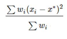 where wi is a weight equal to the value of the pixel based on Data, xi is the x-coordinate of the pixel and x* is the weighted mean.  Note for Detector Rectangle, the value for Data = 0 and 1 will be same because all pixels have same size. Calculations for y* are analogous to those for x*. |
| NSDD (-14 to -15) |
-14, -15: The Geometric MTF in X or Y direction. Results will only be available for Data = 0 or Data = 1, and the results will be the same for both Data inputs. Spatial Frequency is used to specify the spatial frequency (in cycles/millimeter) at which the MTF data is calculated. The Spatial Frequency parameter is only considered when applied to a Detector Rectangle and Pix# is set to -14 or -15. Data is 0 for flux, 1 for flux/area, 2 for flux/solid angle pixel, 3 for normalized flux, 4 for absorbed flux, and 5 for absorbed flux/area. Note Data = 2 is only available for Detector Rectangle, which records data in angle space. Only values 0 and 1 (for flux and flux/area) are supported for faceted detectors. A value of 3 is only supported when Pix# is a positive integer; in this case the returned flux for the pixel is normalized to the peak flux for all consecutive NSDD operands in the Merit Function Editor which refer to the same surface and detector. A value of 3 should generally be used only as a part of the NSC Bitmap Merit Function (see "NSC Bitmap Merit Function Tool"). For Detector Rectangles only: If Pix# is not a positive integer, then a number of edge pixels may be ignored in the calculation if desired. The number of edge pixels that will be ignored is given by the # Ignored input. For non-zero values of # Ignored, the number of pixels accounted for in the calculation will be reduced along all boundaries of the detector. For example, if a detector has 100 pixels in X and 200 pixels in Y and the # Ignored value is 2, then the calculation will be based upon detector data from 96 pixels in X and 196 pixels in Y, with data from the last 2 edge pixels along the left, right, bottom and top boundaries all ignored. The only calculation not affected by the # Ignored input is the number of rays striking the detector, as given by Pix # = -3 (in addition to all values calculated for positive integer inputs to Pix #). For Detector Volumes: Pix# is interpreted as the voxel number. For Data values of 0, 1, or 2, the returned value is incident flux, absorbed flux, or absorbed flux per unit volume, respectively. If Pix# is zero, the value returned is the sum for all pixels. For Object Is A Detector: There are two additional options for data. Data is 4 for absorbed flux and 5 for absorbed flux/area. For Detector Color objects, use NSDE instead. For Detector Polar objects, use NSDP. For information about optimization in Non-Sequential Mode, see "NSC Operands" |
| NSDE (1-11) |
Non-sequential Detector Color object data. Surf defines the surface number of the NSC group (always 1 in pure NSC systems). Det# refers to the object number of the desired detector. If Det# is zero, then all detectors are cleared. If Det# is less than zero, then the detector defined by the absolute value of Det# only is cleared. If Pix# is a positive integer greater than zero, then the data from the specified pixel is returned. Otherwise, the following data is returned depending upon the value of Pix#: 0: Sum of all data for all pixels on the detector. For chromaticity coordinates this is the average over all pixels in the detector that have non-zero lumen values. If Pix# is zero the <area> values described below are the area of the entire detector, measured in analysis units for position space data or solid angle in steradians for angle space data. -1: Maximum data. -2: Minimum data. -3: Number of rays striking the detector. Angle? is 0 for position space data, 1 for angle space data. Data is an integer code that defines the type of data to return, defined as follows: 1: power in <sprefix> watts where <sprefix> is the source units prefix. 2: power/area in <aprefix> watts per <area> where <aprefix> is the analysis units prefix. If Angle? is 0 <area> is the area in analysis units. If Angle? is 1 then <area> is solid angle in steradians. 3: power in <sprefix> lumens where <sprefix> is the source units prefix. 4: power/area in <aprefix> lumens per <area> where <aprefix> is the analysis units prefix. If Angle? is 0 <area> is the area in analysis units. If Angle? is 1 then <area> is solid angle in steradians. 5/6: CIE 1931 chromaticity coordinate x/y. 7/8: CIE 1976 chromaticity coordinate u'/v'. 9/10/11: CIE 1931 tristimulus X/Y/Z value in lumens per <area>. If Angle? is 0 <area> is the area in analysis units. If Angle? is 1 then <area> is solid angle in steradians. |
| NSDE (12-21) |
12/13: Color Rendering Index (CRI) and Correlated Color Temperature (CCT), the latter value in Kelvin. These values are only returned if the option to "Record Spectral Data" has been selected for the Detector Color object (only available in OpticStudio-Premium) and if the Pix# and Angle? are both zero. The returned values are based on the variation of flux with wavelength over the entire detector. 14/15/16: Normalized CIE 1931 tristimulus X/Y/Z value. Identical to the values returned by Data 9, 10, and 11, but normalized to the peak tristimulus Y value for all consecutive NSDE operands in the Merit Function Editor which refer to the same surface and detector. Generally used only as a part of the NSC Bitmap Merit Function (see "NSC Bitmap Merit Function Tool"). Only valid if Pix# is a positive integer and Angle? is zero.zero. 17/18/19/20/21: The Centroid X, Y and RMS radius, X, Y in Specified Spectral Bin. See description of Wavelength Column for specifying the Spectral Bin. See Detector Settings in Type Section of the Object Properties for defining Spectral Range of Bins. Wavelength specifies which Spectral Bin's data is calculated for centroid X/Y and RMS radius/X/Y. If the value of Wavelength is inside one Bin's Spectral Range, the Bin's data will be selected for calculation. See "Record Spectral Data" for details of Spectral Binning. If Pix# is not a positive integer, then a number of edge pixels may be ignored in the calculation if desired. The number of edge pixels that will be ignored is given by the # Ignored input. For non- zero values of # Ignored, the number of pixels accounted for in the calculation will be reduced along all boundaries of the detector. For example, if a detector has 100 pixels in X and 200 pixels in Y and the # Ignored value is 2, then the calculation will be based upon detector data from 96 pixels in X and 196 pixels in Y, with data from the last 2 edge pixels along the left, right, bottom and top boundaries all ignored. Calculations that are not affected by the # Ignored input are the number of rays striking the detector, as given by Pix # = -3, and the CRI and CCT values, as given by Data = 12 and Data = 13, respectively (the # Ignored input also does not affect any values calculated for positive integer inputs to Pix #). If the source units are joules, then the data 1 and 2 are in joules and data 3 and 4 are in talbots. See " Units ". See also NSDD and NSDP. |
| NSDP | Non-sequential Detector Polar object data. Surf defines the surface number of the NSC group (always 1 in pure NSC systems). Det# refers to the object number of the desired detector. If Det# is zero, then all detectors are cleared. If Det# is less than zero, then the detector defined by the absolute value of Det# only is cleared.If Pix# is a positive integer greater than zero, then the data from the specified pixel is returned. Otherwise, the following data is returned depending upon the value of Pix#:0: Sum of all data for all pixels on the detector. For chromaticity coordinates this is the average over all pixels in the detector that have non-zero lumen values.-1: Maximum data.-2: Minimum data.-3: Number of rays striking the detector.-4: The radial RMS in degrees of the distribution with respect to 0 degrees. If Pix# is set equal to -4, then the only valid inputs for Data are 1 or 3. All other inputs will return a value of zero.Data is an integer code that defines the type of data to return, defined as follows:1: power in <sprefix> watts where <sprefix> is the source units prefix.2: power/solid angle in <sprefix> watts per steradian where <sprefix> is the source units prefix.3: power in <sprefix> lumen where <sprefix> is the source units prefix.4: power/solid angle in <sprefix> lumens per steradian where <sprefix> is the source units prefix.5/6: CIE 1931 chromaticity coordinate x/y.7/8: CIE 1976 chromaticity coordinate u'/v'.9/10/11: CIE 1931 tristimulus X/Y/Z value in lumens/steradian.If the source units are joules, then the data 1 and 2 are in joules and data 3 and 4 are in talbots. See " Units ". See also NSDD and NSDE. |
| NSLT | Non-sequential LightningTrace. This operand traces mesh rays as defined by the LightningTrace analysis. Surf is the surface number of the Non-sequential surface. Src# refers to the object number of the desired source from which to trace mesh rays. If Src# is zero, rays will be traced from all sources. Ray Samp defines the sampling to use in defining the ray mesh: 0 = Low (1X), 1 = 4X, 2 = 16X, 3 = 64X, 4 = 256X, 5 = 1024X. Edge Samp defines the sampling to use for resolving the ray mesh around the edges of objects, with the same interpretation for the numeric inputs as for Ray Samp (but with inputs only going from 0 to 4). RT? defines whether mesh rays should be traced (when RT? = 0) or whether all analysis rays should be traced using conventional ray tracing (when RT? = 1). If RT? = 1, then this operand will act just like the NSTR operand with polarization, splitting, and scattering all turned off.An NSDD, NSDE, or NSDP operand with Det# set equal to 0 must be included in the merit function prior to this operand.See " The LightningTrace Control " for more information. See also NSTR. |
| NSRA (1-15) |
Non-sequential single ray trace. Src# refers to the object number of the desired source. This source must be defined to trace just a single analysis ray. If Splt? is non-zero, then splitting is on. If Pol? is non-zero then polarization will be used. If splitting is on polarization is automatically selected. Scattering is always turned off for this feature, since scattering introduces random paths for the child rays, which is not suitable for optimization. Errors are always considered. If multiple NSRA operands trace the same ray are adjacent in the merit function editor, the ray will only be traced once for efficiency. Seg# refers to the segment number that contains the data to be returned. Use -1 for the last segment. Data refers to the data type for the specified segment. Use Data values 1-9 for x-coordinate, y-coordinate, z-coordinate, x-cosine, y-cosine, z-cosine, x- normal, y-normal, and z-normal, respectively. These values are relative to the entry port, see 31- 39 below. Use Data values 10-15 for path-to, intensity, phase of, phase at, index, and starting phase, respectively. Note that the phase at value is not modulo 2*pi, as is the case with ZRD files. |
| NSRA (16-39) |
Use Data values 16-17 for the sum of the path, or optical path, respectively, in lens units from the source to the end of the specified segment. These values do not include the phase of diffractive surfaces. Use Data values 21-26 for Ex real, Ex imaginary, Ey real, Ey imaginary, Ez real, and Ez imaginary, respectively. Polarization must be on for real and imaginary data to be returned. Use Data value 27-29 for the phase of Ex, Ey, and the phase difference between Ex and Ey, respectively. All values are in radians. Polarization must be on for valid data to be returned. Use Data values 31-39 for the coordinate data defined by Data values 1-9 converted to coordinates relative to the global coordinate reference surface. Source # refers to the element number to use if the source is an array; see the "Sources" settings in the Object Properties for the numbering scheme. Note the segments NSRA is not listed in same order as in ZRD. For example, for a same ray, the segment with Seg# =17 in NSRA is not same to the 17th segment listed in ZRD. Note the phase_at (Data = 13) is referenced to the center of the pixel where the ray hits on the detector. See more explanations in section "Ray database (ZRD) files". For more information on these data items see "The ZRD Uncompressed Full Data Format (UFD)". |
| NSRD | Non-sequential Ray Database. "ZRD file" defines the name of the ZRD file to be saved. (up to 140 characters)If the "ZRD format" setting is a positive integer, it defines the format of the ZRD file:0: Uncompressed Full Data1: Compressed Basic Data2: Compressed Full DataIf "ZRD format" is set to -1 then any subsequent NSTR operands will not create a ZRD file.This operand must come before the NSTR operand in the Merit Function. |
| NSRM | Non-sequential Rotation Matrix component. Surf defines the surface number of the NSC group (always 1 in pure NSC systems). Object defines the object number in the NSC group.If Ref? is 0, the coordinates are relative to the reference object. The rotation matrix will always be the identity matrix when using this reference.If Ref? is 1, the coordinates are relative to the origin of the NSC coordinate system or entry port. If Ref? is 2, then the coordinates are relative to the global coordinate reference surface.The 3 x 3 R matrix has 9 components. If Data is 1, NSRM returns R[1][1], if Data is 2, NSRM returns R[1][2], etc... through Data = 9 returning R[3][3]. |
| NSRW | Non-sequential roadway lighting data.Data defines the desired roadway lighting data to be returned. Use 0 for average luminance, 1 for overall uniformity of luminance, 2 for longitudinal uniformity of luminance, 3 for threshold increment,4 for surround ratio, 5 for average illuminance, 6 for minimum illuminance, and 7 for uniformity ofhorizontal illuminance. The arguments # Lanes, Lane Width, Spacing, and Offset are all asdefined for the roadway lighting analysis. Arrange defines the luminaire arrangement along the roadway. Use 0 for single-side, 1 for double-sided, and 2 for staggered. Surf. Class defines theroad surface classification. Use 0 for R1, 1 for R2, 2 for R3, and 3 for R4.See "Roadway Lighting" for more information.The first NSRW with unique settings must be immediately preceded by an NSTW operand in order to compute data. NSRW operands with the same settings (except Data) must be placed on adjacent lines. These subsequent operands will simply return data cached by the first NSRW operand. This operand is intended to be used as part of the NSC Roadway Merit Function Tool.See "NSC Roadway Merit Function Tool" for more information. |
| NSST | Non-sequential single ray trace. This operand traces a single sequential ray through the system to any specified Non-sequential surface, and returns various data about the ray within the Non- Sequential surface. Surf is the surface number of the Non-sequential surface. Wave is the wavelength number. For a definition of Hx, Hy, Px, and Py, see "Hx, Hy, Px, and Py". Data determines what data NSST will compute and return as follows:0, 1, 2: The x, y, or z coordinate at the ray-object intercept point.3, 4, 5: The x, y, or z direction cosines of the ray after reflection/refraction from the surface.6, 7, 8: The x, y, or z direction cosines of the ray up to the ray-object intercept point.9, 10, 11: The surface normal at the ray-object intercept point.12: The face number of the object the ray struck.Object specifies which object the desired data is for.In the general case, a ray may strike the same object multiple times. By default, NSST will return the data for the last intercept on the specified object. To select a specific intercept, add 1000 to the Data value for each time the ray strikes the object. For example, to compute the y coordinate value of the ray on the third time the ray strikes an object, use a Data value of 3001. If the ray does not strike the object, or does not strike the object the specified number of times, the operand returns a value of zero, but no warning or error is issued.All coordinates and cosines are in the coordinate system of the Non-sequential surface. An NSDC, NSDD, NSDE, or NSDP operand with Det# set equal to 0 must be included in the merit function prior to this operand. See also NSTR. |
| NSTR | Non-sequential trace. Src# refers to the object number of the desired source. If Src# is zero, all sources will be traced. If Splt? is non-zero, then splitting is on. If Scat? is non-zero, then scattering is on. If Pol? is non-zero then polarization will be used. If splitting is on polarization is automatically selected. If IgEr? is non-zero, then errors will be ignored. See "Optimizing with sources and detectors in non-sequential mode" for complete details.An NSDD, NSDE, or NSDP operand with Det# set equal to 0 must be included in the merit function prior to this operand.See also NSST. |
| NSTW | Non-sequential roadway lighting raytrace. This operand is solely for optimizing roadway lighting applications in conjunction with the NSRW operand and the NSC Roadway Merit Function. If Splt? is non-zero, then splitting is on. If Scat? is non-zero, then scattering is on. If Pol? is non-zero then polarization will be used. If splitting is on polarization is automatically selected. If IgEr? is non-zero, then errors will be ignored. Origin is the row number of the origin object. MH is the mounting height used in the calculation.See "Roadway Lighting" for more information.NSTW should be immediately followed by an NSRW operand to compute data. This operand is intended to be used as part of the NSC Roadway Merit Function Tool.See "NSC Roadway Merit Function Tool" for more information. |
| NTXG | Non-sequential object tilt about x greater than. See NPXG. |
| NTXL | Non-sequential object tilt about x less than. See NPXG. |
| NTXV | Non-sequential object tilt about x value. See NPXG. |
| NTYG | Non-sequential object tilt about y greater than. See NPXG. |
| NTYL | Non-sequential object tilt about y less than. See NPXG. |
| NTYV | Non-sequential object tilt about y value. See NPXG. |
| NTZG | Non-sequential object tilt about z greater than. See NPXG. |
| NTZL | Non-sequential object tilt about z less than. See NPXG. |
| NTZV | Non-sequential object tilt about z value. See NPXG. |
| OBSN | Object space numerical aperture. This is only useful for finite conjugate systems, and is calculated on axis at the primary wavelength. |
| OOFF | This operand indicates an unused entry in the operand list. OOFF operands are automatically converted to BLNK operands upon evaluation of the merit function. OOFF is only used to indicate that the merit function operand type was not recognized. |
| OPDC | Optical path difference with respect to chief ray in waves at the wavelength defined by Wave. See "Hx, Hy, Px, and Py". |
| OPDM | Optical path difference with respect to the mean OPD over the pupil at the wavelength defined by Wave. OPDM has the same restrictions that TRAC does; see TRAC for a detailed discussion. See "Hx, Hy, Px, and Py". |
| OPDX | Optical path difference with respect to the mean OPD over the pupil with tilt removed at the wavelength defined by Wave. OPDX has the same restrictions that TRAC does; see TRAC for a detailed discussion. See "Hx, Hy, Px, and Py". |
| OPGT | Operand greater than. This is used to make the value of the operand defined by Op# greater than the target value. |
| OPLT | Operand less than. This is used to make the value of the operand defined by Op# less than the target value. |
| OPTH | Optical path length. This is the distance, in lens units, the specified ray travels to the surface defined by Surf at the wavelength defined by Wave. The distance is measured from the object for finite conjugates. This distance is meaningless for infinite conjugates, and the optical path length starts to be calculated from a reference phase plane tangent to the chief ray intercept at the first surface. The optical path accounts for the index of refraction of the media, and for phase adding surfaces such as gratings and binary optics. See PLEN. See "Hx, Hy, Px, and Py". |
| OPVA | Operand value. This operand constrains the value of the operand defined by Op# to be equal to the target value. |
| OSCD | Offense against the sine condition (OSC) at the wavelength defined by Wave. There are two definitions for OSC supported. The first definition is as described in Welford, Aberrations of Optical Systems (see "References on Lens Design"). This definition is used if Zone is zero. An alternate definition due to Prof. Roland Shack which supports computation of OSC as a function of pupil zone and uses only real rays is available. This definition is used if Zone is not zero. In this case, Zone corresponds to the Py coordinate of the real marginal ray. The two methods will give very similar results for systems with modest F/#'s and aberrations when Zone is 1.0 for the alternate definition. This operand has no meaning if the system is not axially symmetric. |
| OSUM | Sums the values of all operands between the two operands defined by Op#1 and Op#2. See SUMM. |
| PANA | Paraxial ray x-direction surface normal at the ray-surface intercept at the wavelength defined by Wave. This is the x component of the surface normal vector at the intersection point of the specified paraxial ray and the surface defined by Surf, in the local coordinate system. See "Hx, Hy, Px, and Py". |
| PANB | Paraxial ray y-direction surface normal at the ray-surface intercept at the wavelength defined by Wave. This is the y component of the surface normal vector at the intersection point of the specified paraxial ray and the surface defined by Surf, in the local coordinate system. See "Hx, Hy, Px, and Py". |
| PANC | Paraxial ray z-direction surface normal at the ray-surface intercept at the wavelength defined by Wave. This is the z component of the surface normal vector at the intersection point of the specified paraxial ray and the surface defined by Surf, in the local coordinate system. See "Hx, Hy, Px, and Py". |
| PARA | Paraxial ray x-direction cosine of the ray after refraction from the surface defined by Surf at the wavelength defined by Wave. See "Hx, Hy, Px, and Py". |
| PARB | Paraxial ray y-direction cosine of the ray after refraction from the surface defined by Surf at the wavelength defined by Wave. See "Hx, Hy, Px, and Py". |
| PARC | Paraxial ray z-direction cosine of the ray after refraction from the surface defined by Surf at the wavelength defined by Wave. See "Hx, Hy, Px, and Py". |
| PARR | Paraxial ray radial coordinate in lens units at the surface defined by Surf at the wavelength defined by Wave. This is the radial distance from the local axis to the intersection of the surface defined by Surf and the specified paraxial ray, in the local coordinate system. See "Hx, Hy, Px, and Py". |
| PARX | Paraxial ray x-coordinate in lens units at the surface defined by Surf at the wavelength defined by Wave. See "Hx, Hy, Px, and Py |
| PARY | Paraxial ray y-coordinate in lens units at the surface defined by Surf at the wavelength defined by Wave. See "Hx, Hy, Px, and Py". |
| PARZ | Paraxial ray z-coordinate in lens units at the surface defined by Surf at the wavelength defined by Wave. See "Hx, Hy, Px, and Py". |
| PATX | Paraxial ray x-direction ray tangent. This is the tangent of the angle the paraxial ray makes in the X-Z plane after refraction from surface defined by Surf at the wavelength defined by Wave. See "Hx, Hy, Px, and Py". |
| PATY | Paraxial ray y-direction ray tangent. This is the tangent of the angle the paraxial ray makes in the Y-Z plane after refraction from surface defined by Surf at the wavelength defined by Wave. See "Hx, Hy, Px, and Py". |
| PETC | Petzval curvature in inverse lens units at the wavelength defined by Wave. Not valid for non-paraxial systems. |
| PETZ | Petzval radius of curvature in lens units at the wavelength defined by Wave. Not valid for non- paraxial systems. |
| PIMH | Paraxial image height at the paraxial image surface at the wavelength defined by Wave. Not valid for non-paraxial systems. |
| PLEN | Path length. This operand computes the total optical path length (including index of refraction and phase surfaces) between surfaces Surf1 and Surf2 for the specified ray, which is always traced at the primary wavelength. PLEN is essentially the difference between two OPTH operands. See OPTH. See "Hx, Hy, Px, and Py". |
| PMAG | Paraxial magnification. This is the ratio of the paraxial chief ray height on the paraxial image surface to the object height at the wavelength defined by Wave. Only useful for finite conjugate systems. Note the paraxial image surface is used even if the system is not at paraxial focus. |
| PMGT | Parameter greater than. This boundary operand constrains the value of the parameter defined by Param for the surface defined by Surf to be greater than the target value. The parameter values have different meanings depending upon the surface type. See the Chapter "Surface Types" for a description of the parameter values. |
| PMLT | Parameter less than. This boundary operand constrains the value of the parameter defined by Param for the surface defined by Surf to be less than the target value. The parameter values have different meanings depending upon the surface type. See the Chapter "Surface Types" for a description of the parameter values. |
| PMVA | Parameter value. This boundary operand constrains the value of the parameter defined by Param for the surface defined by Surf to be equal to the target value. The parameter values have different meanings depending upon the surface type. See the Chapter "Surface Types" for a description of the parameter values. |
| PnGT | This operand is obsolete, use PMGT instead. |
| PnLT | This operand is obsolete, use PMLT instead. |
| PnVA | This operand is obsolete, use PMVA instead. |
| POPD (1-26) |
Physical Optics Propagation Data. For important details see "About Physical Optics Propagation".To use this operand, first define the settings on the POP analysis feature as desired, then press Save on the settings box. The operand will return data based upon the selected settings. If Surf is zero, then the saved ending surface number will be used; otherwise, the specified surface will be used as the ending surface. If Wave is zero, then the saved wavelength number will be used; otherwise, the specified wavelength number will be used. If Field is zero, then the saved field number will be used; otherwise, the specified field number will be used. Data determines what data the POP feature will compute and return as follows: 0: The total fiber coupling. This is the product of the system efficiency and the receiver efficiency. 1: The system efficiency for fiber coupling. 2: The receiver efficiency for fiber coupling. 3: The total power. 4: The peak irradiance. 5, 6, 7: The pilot beam position, Rayleigh range, beam waist (x). 8, 9, 10: The pilot beam position, Rayleigh range, beam waist (y). 11, 12, 13: The local X, Y, Z coordinates of the center of the beam array on the end surface (this is a reference point and is not related to the amplitude of the beam). 21, 22: The X, Y coordinates of the centroid of the intensity distribution in local coordinates relative to the center of the beam. The orientation of the X/Y axes for this result are not necessarily the same as the orientation of the end surface. 23, 24, 25, 26: The X, Y beam width and X, Y M-squared values, respectively. For data 23, 24 with default Xtr1 value set to 0 beam widths are calculated in the lab coordinate system. When Xtr1 value set to 1 beam widths are calculated in the direction of its principle axes. Note when calculating M-squared value for asymmetric beams, the "Separate X, Y" must be checked when clicking the "Save" button in the POP analysis setting dialog. See "Beam width and M-squared". |
| POPD (27-63) |
27: The square root of second moment of the beam for x 2, θ x 2, xθ x, and xθ y for Xtr1 values 0, 1, 2, and 3, respectively. 28: The square root of second moment of the beam for y 2, θ y 2, yθ y, and yθ x for Xtr1 values 0, 1, 2, and 3, respectively. 29: The square root of second moment of the beam for xy and θ x θ y for Xtr1 values 0 and 1, respectively. 30, 31, 32: The mean, RMS and PTV irradiance variation, respectively, of the non-zero amplitude portion of the beam. These operands should only be used when the beam has nearly uniform irradiance and has just been clipped by a surface aperture. 33, 34, 35: The mean, RMS and PTV phase variation in radians, respectively, of the non-zero amplitude portion of the beam. These operands should only be used when the beam has nearly uniform irradiance and has just been clipped by a surface aperture. 40, 41, 42: The fraction of the total power enclosed within a circle of radius specified by the Xtr1 value in lens units, referenced to the beam centroid (40), chief ray (41), or surface vertex (42). 50, 51, 52: The radius in lens units of the circle at which the fraction of the total power enclosed is equal to the value specified by the Xtr1 value. The circle is centered on the beam centroid (50), chief ray (51), or surface vertex (52). 60, 61, 62, 63: The fiber coupling receiver efficiency amplitude and phase in radians for the Ex field (60 and 61) and the Ey field (62 and 63). These values do not consider system efficiency (see Data type 1 above). Data inputs 60-63 request a polarized POP calculation, but if the input beam is unpolarized, the field coupling efficiency amplitudes and phases are not physically well-defined. Therefore, values of 0.0 will be returned if the input beam is unpolarized. Undefined Data values will return 0. The Xtr1 and Xtr2 values are only used by selected data numbers which are reserved for future expansion of this feature.If adjacent POPD operands all have the same Surf, Wave, Field, Xtr1, and Xtr2 values, then the POP analysis is done just once and all data returned at one time. Note the POPD operands must be on adjacent rows in the MFE for this efficiency to be implemented. |
| POPI | Physical Optics Propagation Data. For important details see "About Physical Optics Propagation".To use this operand, first define the settings on the POP analysis feature as desired, then pressSave on the settings box. The operand will return data based upon the selected settings.If Surf is zero, then the saved ending surface number will be used; otherwise, the specified surface will be used as the ending surface. If Wave is zero, then the saved wavelength number will be used; otherwise, the specified wavelength number will be used. If Field is zero, then the saved field number will be used; otherwise, the specified field number will be used.Data determines what data the POP feature will compute and return as follows:0, 1, 2: The total (Ex + Ey), Ex only, or Ey only Irradiance.3, 4, 5, 6: Ex-real, Ex-Imaginary, Ey-real, Ey-imaginary.7, 8: Ex, Ey phase in radians. Undefined Data values will return 0.The Pix# refers to the desired pixel of the beam. The pixel number is greater than or equal to zero, and less than nx*ny, where nx and ny are the number of columns and rows, respectively. The pixel number is generally defined as p = x + y*nx where x is the integer row number and y is the integer column number, and 0 <= x < nx and 0 <= y < ny.If adjacent POPI operands all have the same Surf, Wave, and Field values, then the POP analysis is done just once and all data returned at one time. Note the POPI operands must be on adjacent rows in the MFE for this efficiency to be implemented. |
| POWF | Power at a field point. Computes the power or effective focal length (EFL) after refraction from the surface defined by Surf at the wavelength defined by Wave for any point in the field. For the Data parameter, use 0 for spherical, 1 for cylinder, 2 for max, 3 for min, 4 for tangential, 5 for sagittal, 6 for y, 7 for x, and 8 for astigmatic power in diopters. To get the EFL values, add 9 to these codes. For example, for tangential EFL use Data = 13. For cylinder, the EFL value is the difference between the maximum and minimum focal lengths. For astigmatic, the EFL is the difference between the x and y direction focal lengths (x-y). For a full description of this type of analysis, see "Power Field Map". See "Hx, Hy, Px, and Py". |
| POWP | Power at a point in the pupil. Computes the power or effective focal length (EFL) after refraction from the surface defined by Surf at the wavelength defined by Wave for any point in the field, at any point in the pupil. For the Data parameter, use 0 for spherical, 1 for cylinder, 2 for max, 3 for min, 4 for tangential, 5 for sagittal, 6 for y, 7 for x, and 8 for astigmatic power in diopters. To get the EFL values, add 9 to these codes. For example, for tangential EFL use Data = 13. For cylinder, the EFL value is the difference between the maximum and minimum focal lengths. For astigmatic, the EFL is the difference between the x and y direction focal lengths (x-y). For a full description of this type of analysis, see " Power Pupil Map ". See "Hx, Hy, Px, and Py". |
| POWR | The surface power (in inverse lens units) of the surface defined by Surf at the wavelength defined by Wave. This operand only works for standard surfaces. |
| PRIM | Primary wavelength. This is used to change the primary wavelength number to the wavelength defined by Wave during merit function evaluation. This operand does not use the target or weight columns. |
| PROB | Multiplies the value of the operand defined by Op# by the factor defined by Factor. |
| PROD | Product of two operands (Op#1 X Op#2). See PROB. |
| PSLP | The phase slope in periods of 2p per lens unit, at the primary system wavelength of the surface defined by Surf at a specific point on the XY plane. This operand has Mode, X, Y, Remove, and Orientation inputs. Aperture is not considered and values will be returned for any XY coordinate. If the surface number specified is not a phase surface (such as Binary, Diffraction Grating, Grid Phase, etc.) no value is returned. For Mode = 0 or 1, the X and Y coordinates are in lens units. For Mode = 2, the coordinates Xn and Yn are normalized by the clear semi-diameter. For Remove = 0 (default), no data is removed. For Remove = 1, any constant value at the vertex of the part is removed from the phase data before calculating the phase slope . For Remove = 2, the tilt term is removed from the phase data before calculating the phase slope. For Remove = 3, the power term is removed from the phase data before calculating the phase slope. Orientation selects the direction of the slope calculation. Orientation = 0 (default) calculated along the tangential direction (radially outward). Orientation = 1 calculated along the sagittal direction (orthogonal to radially outward). Orientation = 2 calculated along the X-axis direction. Orientation = 3 calculated along the Y-axis direction. Orientation = 4 is the modulus, or full length of the slope vector, at the orientation angle that contains the full length of the vector. (The orientation angle is not explicitly calculated and can vary between points on the slope map). Note that sampling is set to 33x33. See also QSLP. |
| QOAC | Unused. |
| QSLP | Returns data about the phase slope at the primary system wavelength of the surface defined
by Surf. This operand has Data, Sampling, Remove, and Orientation inputs. If the surface number
specified is not a phase surface (such as Binary, Diffraction Grating, Grid Phase, etc.) no
value is returned. The options for the Data inputs are: 1 – RMS phase slope value over the surface. 2 – PV phase slope value over the surface. 3 – Minimum phase slope value over the surface. 4 – Maximum phase slope value over the surface. 5 – X coordinate for the point on the surface with the minimum phase slope value. 6 – Y coordinate for the point on the surface with the minimum phase slope value. 7 – X coordinate for the point on the surface with the maximum phase slope value. 8 – Y coordinate for the point on the surface with the maximum phase slope value. 9 – Value of the constant phase, if removed from the phase data. 10 – Value of the tilt about X, if removed from the phase data. 11 – Value of the tilt about Y, if removed from the phase data. 12 – Value of the power, if removed from the phase data. The options for the Samp input are: 1 – 33 x 33 (default) 2 – 65 x 65 3 – 129 x 129 4 – 257 x 257 5 – 513 x 513 6 – 1025 x 1025 7 – 2049 x 2049 8 – 4097 x 4097 9 – 8193 x 8193 10 – 16385 x 16385 For Remove = 0 (default), no data is removed. For Remove = 1, any constant value at the vertex of the part is removed from the phase data before calculating the phase slope . For Remove = 2, the tilt term is removed from the phase data before calculating the phase slope. For Remove = 3, the power term is removed from the phase data before calculating the phase slope. Orientation selects the direction of the slope calculation. Orientation = 0 (default) calculated along the tangential direction (radially outward). Orientation = 1 calculated along the sagittal direction (orthogonal to radially outward). Orientation = 2 calculated along the X-axis direction. Orientation = 3 calculated along the Y-axis direction. Orientation = 4 is the modulus, or full length of the slope vectors. See also PSLP. |
| QSUM | Quadratic sum. This operand squares and then adds all operands between the two operands defined by Op#1 and Op#2, then takes the square root of the sum. See also SUMM, OSUM, EQUA. |
| RAED | Real ray angle of exitance. This is the angle in degrees between the surface normal and the ray after refraction or reflection for the surface defined by Surf at the wavelength defined by Wave. See also RAID. See "Hx, Hy, Px, and Py". |
| RAEN | Real ray angle of exitance. This is the cosine of the angle between the surface normal and the ray after refraction or reflection at the surface defined by Surf at the wavelength defined by Wave. See also RAIN. See "Hx, Hy, Px, and Py". |
| RAGA |
Global ray x-direction cosine of the ray after refraction from the surface defined by Surf at the wavelength defined by Wave. See "Hx, Hy, Px, and Py". The origin of the global coordinate system is at the global reference surface. |
| RAGB | Global ray y-direction cosine. See RAGA. |
| RAGC | Global ray z-direction cosine. See RAGA. |
| RAGX | Global ray x-coordinate. This is the coordinate in lens units in the global coordinate system at the surface defined by Surf at the wavelength defined by Wave. The origin of the global coordinate system is at the global reference surface. See "Hx, Hy, Px, and Py". |
| RAGY | Global ray y-coordinate. See RAGX. |
| RAGZ | Global ray z-coordinate. See RAGX. |
| RAID | Real ray angle of incidence. This is the angle in degrees between the surface normal and the incident ray at the surface defined by Surf at the wavelength defined by Wave. Note the angle of incidence is always positive. See also RAED. See "Hx, Hy, Px, and Py". |
| RAIN | Real ray angle of incidence. This is the cosine of the angle between the surface normal and the ray before refraction at the surface defined by Surf at the wavelength defined by Wave. See also RAEN. See "Hx, Hy, Px, and Py". |
| RANG | Ray angle in radians with respect to z axis. The angle is measured with respect to the local Z axis of the surface defined by Surf at the wavelength defined by Wave. See "Hx, Hy, Px, and Py". |
| REAA | Real ray x-direction cosine of the ray after refraction from the surface defined by Surf at the wavelength defined by Wave. See "Hx, Hy, Px, and Py". |
| REAB | Real ray y-direction cosine of the ray after refraction from the surface defined by Surf at the wavelength defined by Wave. See "Hx, Hy, Px, and Py". |
| REAC | Real ray z-direction cosine of the ray after refraction from the surface defined by Surf at the wavelength defined by Wave. See "Hx, Hy, Px, and Py". |
| REAR | Real ray radial coordinate in lens units at the surface defined by Surf at the wavelength defined by Wave. See "Hx, Hy, Px, and Py". |
| REAX | Real ray x-coordinate in lens units at the surface defined by Surf at the wavelength defined by Wave. See "Hx, Hy, Px, and Py". |
| REAY | Real ray y-coordinate in lens units at the surface defined by Surf at the wavelength defined by Wave. See "Hx, Hy, Px, and Py". |
| REAZ | Real ray z-coordinate in lens units at the surface defined by Surf at the wavelength defined by Wave. See "Hx, Hy, Px, and Py". |
| RECI | Returns the reciprocal of the value of operand Op#1. See also "DIVI". |
| RELI | Relative illumination. This operand computes the relative illumination of the field point defined by Field relative to the (0, 0) field point. Note that in some systems, the illumination increases off axis, and for these systems the RI may be greater than one since the RELI operand uses (0, 0) as a reference field point. Vignetting factors are always removed for this calculation. The other parameters are:Samp: The grid size. A value of 10 would yield a 10 x 10 grid of rays.Wave: The wavelength number to use.Pol?: Set to 0 to ignore polarization and 1 to consider it. See also EFNO. |
| RENA | Real ray x-direction surface normal at the ray-surface intercept at the surfaced defined by Surf at the wavelength defined by Wave. See "Hx, Hy, Px, and Py". |
| RENB | Real ray y-direction surface normal at the ray-surface intercept at the surface defined by Surf at the wavelength defined by Wave. See "Hx, Hy, Px, and Py". |
| RENC | Real ray z-direction surface normal at the ray-surface intercept at the surface defined by Surf at the wavelength defined by Wave. See "Hx, Hy, Px, and Py". |
| RETX | Real ray x-direction ray tangent (slope) at the surface defined by Surf at the wavelength defined by Wave. See "Hx, Hy, Px, and Py". |
| RETY | Real ray y-direction ray tangent (slope) at the surface defined by Surf at the wavelength defined by Wave. See "Hx, Hy, Px, and Py". |
| RGLA | Reasonable glass. This operand restricts the deviation the index, Abbe, and deviation of the partial dispersion values may take from actual glasses in the currently loaded glass catalogs. See "Optimizing zoom and multi-configuration lenses" for a complete discussion including a description of Wn, Wa and Wp. The constraint is active over the surface range specified by Surf1 and Surf2. |
| RSCE | RMS spot radius with respect to the centroid in lens units. This operand uses a Gaussian quadrature method that is accurate for systems with unvignetted circular pupils. Ring is used to specify the number of rings of rays traced. If Wave is zero; then a wavelength weighted polychromatic calculation is performed; otherwise, the specified wavelength number will be used. See "Hx, Hy, Px, and Py". |
| RSCH | RMS spot radius with respect to the chief ray in lens units. This operand uses a Gaussian quadrature method that is accurate for systems with unvignetted circular pupils. Ring is used to specify the number of rings of rays traced. If Wave is zero; then a wavelength weighted polychromatic calculation is performed; otherwise, the specified wavelength number will be used. See "Hx, Hy, Px, and Py". |
| RSRE | RMS spot radius with respect to the centroid in lens units. This operand uses a rectangular grid of rays to estimate the RMS. This operand considers vignetting. A Samp value of n will trace an n x n grid per pupil quadrant. If Wave is zero; then a wavelength weighted polychromatic calculation is performed; otherwise, the specified wavelength number will be used. See "Hx, Hy, Px, and Py". |
| RSRH | RMS spot radius with respect to the chief ray in lens units. This operand uses a rectangular grid of rays to estimate the RMS. This operand considers vignetting. A Samp value of n will trace an n x n grid per pupil quadrant. If Wave is zero; then a wavelength weighted polychromatic calculation is performed; otherwise, the specified wavelength number will be used. See "Hx, Hy, Px, and Py". |
| RWCE | RMS wavefront error with respect to the centroid in waves. This operand uses a Gaussian quadrature method that is accurate for systems with unvignetted circular pupils. Ring is used to specify the number of rings of rays traced. If Wave is zero; then a wavelength weighted polychromatic calculation is performed; otherwise, the specified wavelength number will be used. See "Hx, Hy, Px, and Py". |
| RWCH | RMS wavefront error with respect to the chief ray in waves. This operand uses a Gaussian quadrature method that is accurate for systems with unvignetted circular pupils. Ring is used to specify the number of rings of rays traced. If Wave is zero; then a wavelength weighted polychromatic calculation is performed; otherwise, the specified wavelength number will be used. See "Hx, Hy, Px, and Py". |
| RWRE | RMS wavefront error with respect to the centroid in waves. This operand uses a rectangular grid of rays to estimate the RMS. This operand considers vignetting. A Samp value of n will trace an n x n grid per pupil quadrant. If Wave is zero; then a wavelength weighted polychromatic calculation is performed; otherwise, the specified wavelength number will be used. See "Hx, Hy, Px, and Py". |
| RWRH | RMS wavefront error with respect to the chief ray in waves. This operand uses a rectangular grid of rays to estimate the RMS. This operand considers vignetting. A Samp value of n will trace an n x n grid per pupil quadrant. If Wave is zero; then a wavelength weighted polychromatic calculation is performed; otherwise, the specified wavelength number will be used. See "Hx, Hy, Px, and Py". |
| SAGX | The sag in lens units of the surface defined by Surf at X = the clear semi-diameter or semi-diameter, and Y = 0. See also SSAG. |
| SAGY | The sag in lens units of the surface defined by Surf at Y = the clear semi-diameter or semi-diameter, and X = 0. See also SSAG. |
| SCRV |
The curvature in lens units of the surface defined by Surf at the coordinate defined by X and Y, as measured in Lens Units within the coordinate system being used (see "Off-axis" below). This operand has mode, off-axis, remove, best-fit sphere (BFS), and Orientation flags.
|
| SCUR | Surface Curvature. Computes curvature and related data of the surface defined by Surf at the coordinate defined by X and Y. In all cases below, the "maximum" data is determined by calculation of the curvature at 50 points equally spaced from the vertex of the surface to the specified X and Y coordinate, and the largest absolute value found is returned.If data is 0-3, the returned value is the tangential, sagittal, tangential-sagittal, or maximum tangential-sagittal curvature, respectively.If data is 4-7, the returned value is the x, y, x-y, or maximum x-y curvature, respectively.If data is 8-9, the returned value is the absolute value of (R*Sc), where R is the radial coordinate and Sc is the sagittal curvature, or the maximum of this value, respectively. |
| SDRV | Surface Derivative. Computes the first or second derivative of the surface sag (along the local Z axis) of the surface defined by Surf at the coordinate defined by X and Y.If data is 0 or 1, the returned value is the first derivative in the tangential or sagittal direction.If data is 2 or 3, the returned value is the second derivative in the tangential or sagittal direction. |
| SFNO | Sagittal working F/#, computed at the field point defined by Field and the wavelength defined by Wave. See TFNO. |
| SINE | Sine of the value of the operand defined by Op#. If Flag is 0, then the units are radians, otherwise, degrees. |
| SKIN | Skip if not symmetric. See SKIS. |
| SKIS | Skip if symmetric. If the lens is rotationally symmetric, then computation of the merit function continues at the operand defined by Op#. |
| SMIA | SMIA-TV Distortion. Field is the zero distortion reference field position, or use zero to indicate the field position (0, 0). Wave is the wavelength number, or use zero for the primary wavelength. X- Width and Y-Width are the full field width in field units. For more information see "SMIA-TV Distortion". |
| SPCH | Spherochromatism in lens units. This is the difference between the real marginal axial color and the paraxial axial color of the two extreme wavelengths defined by Minw and Maxw. The distance is measured along the Z axis. Zone defines the zone for which the real marginal axial color is computed. Zone corresponds to the Py coordinate of the real marginal ray. Not valid for non-paraxial systems. |
| SPHA | Spherical aberration in waves contributed by the surface defined by Surf at the wavelength defined by Wave. If Surf is zero, the sum for the entire system is used. This is the third order spherical aberration calculated from the Seidel coefficients, and is not valid for non-paraxial systems. |
| SPHS |
The phase in waves at the primary system wavelength of the surface defined by Surf at the coordinate defined by X and Y, as measured in Lens Units. This operand has data and remove flags.
Note that sampling is set to 33x33. See also DPHS. |
| SQRT | Square root of the operand defined by Op#. |
| SSAG |
The sag in lens units of the surface defined by Surf at the coordinate defined by X and Y, as measured in Lens Units within the coordinate system being used (see "Off-axis" below). This operand has mode, off-axis, remove, and best-fit sphere (BFS) flags.
Note that sampling is set to 33x33. See also DSAG, SAGX, SAGY. |
| SSLP |
The slope in lens units of the surface defined by Surf at the coordinate defined by X and Y, as measured in Lens Units within the coordinate system being used (see "Off-axis" below). This operand has mode, off-axis, remove, best-fit sphere (BFS), and Orientation flags.
Note that sampling is set to 33x33. See also DSLP. |
| STHI | Surface Thickness. This operand computes the thickness of the surface defined by Surf to the next surface at the coordinate defined by X and Y on the surface. This operand has a mode flag. Mode = 0 (default) to use Mech Semi-Dia and Mode = 1 to use Clear Semi-Dia value displayed on the Lens Data Editor. The calculation accounts for the sag and center thickness of the surface and the sag of the next surface, but not any tilts and decenters between the surfaces. |
| STRH | Strehl Ratio. This operand computes the Strehl Ratio using the Huygens PSF computation (see "Huygens PSF"). The parameters are:Samp: The pupil sampling, where 1 yields 32 x 32, 2 yields 64 x 64 etc. The sampling is assumed to be the same for both pupil and image.Wave: The wavelength number to use (use 0 for polychromatic).Field: The field number.Pol?: Set to 0 to ignore polarization and 1 to consider it.All Conf?: Set to 0 to use the current configuration (defined by the last CONF operand preceding this operand), and 1 to sum over all configurations. See "Huygens PSF" for a full discussion of this option.By default, the image delta used in the Huygens PSF computation for the evaluation of this operand is 2x smaller than the nominal default image delta. See "Huygens PSF" for the formula used to calculate the nominal default image delta. This is done to zoom in on the peak of the PSF, allowing for a more accurate computation of the Strehl ratio. As a result, the value reported will, in general, be different than the value reported using the nominal default image delta in the Huygens PSF analysis. |
| SUMM | Sum of two operands (Op#1 + Op#2). See OSUM. |
| SVIG | Sets the vignetting factors for the current configuration. The Precision is either 0, 1, or 2; for high, medium, or low precision, respectively. The SVIG operand can take a significant time to execute at high precision, although the resulting optimization is generally superior. Note that the operands SVIG and CVIG only modify the vignetting factors for evaluating subsequent optimization operands. When the end of the merit function is reached, the vignetting factors will be restored to their original values. See also "CVIG". |
| TANG | Tangent of the value of the operand defined by Op#. If Flag is 0, then the units are radians, otherwise, degrees. |
| TCGT | Thermal Coefficient of expansion greater than. This boundary operand constrains the TCE of the surface defined by Surf to be greater than the specified target value. |
| TCLT | Thermal Coefficient of expansion less than. This boundary operand constrains the TCE of the surface defined by Surf to be less than the specified target value. |
| TCVA | Thermal Coefficient of expansion value. This boundary operand constrains the TCE of the surface defined by Surf to be equal to the specified target value. For glass surfaces, see "GTCE". |
| TFNO | Tangential working F/#, computed at the field point defined by Field and the wavelength defined by Wave. See SFNO. |
| TGTH | Sum of glass thicknesses from Surf1 to Surf2. Note that the sum is inclusive, it is not the thickness between the two surfaces. This sum includes all non-air materials. To account for air gaps, see TTHI. |
| TMAS | Total mass. Computes the mass of the glass lenses within the range of surfaces from Surf1 to Surf2. This operand has a mode flag. Mode = 0 (default) to use Mech Semi-Dia and Mode = 1 to use Clear Semi-Dia value displayed on the Lens Data Editor. The mass of a surface considers the volume enclosed up to the following surface; therefore to compute the mass of a single element the first and last surface numbers should be the same. See "Comments on computing element volumes" for a discussion of how element masses and volumes are computed. |
| TOLR | Tolerance data. Data is 0 for RSS estimated change in performance, 1 for nominal performance, and 2 for estimated performance (nominal plus estimated change). File is the integer number corresponding to the tolerance settings file to use. Config# is -2 for the configuration defined by the last CONF operand, -1 for all configurations, 0 to use the configuration set in the tolerance settings file and 1 or greater for a specific configuration number. For details, see "Optimizing tolerance sensitivity" . |
| TOTR | Total track (length) of lens in lens units. See "Total track". |
| TRAC | Transverse aberration radial direction measured in image space with respect to the centroid for the wavelength defined by Wave. Unlike most other operands, TRAC critically depends upon the placement of other TRAC operands within the Merit Function Editor to work correctly. TRAC operands must be grouped together by field position and wavelength. OpticStudio traces all TRAC rays with a common field point together, and then uses the collective data to compute the centroid of all the rays. Each ray individually is then referenced to the computed centroid. This operand should only be entered into the Merit Function Editor by the Sequential Merit Function tool, and is not recommended for use directly by the user. See "Hx, Hy, Px, and Py". |
| TRAD | The x component of the TRAR only. TRAD has the same restrictions that TRAC does; see TRAC for a detailed discussion. |
| TRAE | The y component of the TRAR only. TRAE has the same restrictions that TRAC does; see TRAC for a detailed discussion. |
| TRAI | Transverse aberration radius measured at the surface defined by Surf at the wavelength defined by Wave with respect to the chief ray. Similar to TRAR, except a surface other than the image surface may be specified. See "Hx, Hy, Px, and Py". |
| TRAN | Unused. |
| TRAR | Transverse aberration radial direction measured in image space at the wavelength defined by Wave with respect to the chief ray. See ANAR. See "Hx, Hy, Px, and Py". |
| TRAX | Transverse aberration x direction measured in image space at the wavelength defined by Wave with respect to the chief ray. See "Hx, Hy, Px, and Py". |
| TRAY | Transverse aberration y direction measured in image space at the wavelength defined by Wave with respect to the chief ray. See "Hx, Hy, Px, and Py. |
| TRCX | Transverse aberration x direction measured in image space with respect to the centroid. TRCX has the same restrictions that TRAC does; see TRAC for a detailed discussion. |
| TRCY | Transverse aberration y direction measured in image space with respect to the centroid. TRCY has the same restrictions that TRAC does; see TRAC for a detailed discussion. |
| TSAG | The sag in lens units of the surface defined by Surf at the normal incidence and surface vertex, but in arbitrary direction with an arbitrary reference point. This operand has modes, X, Y and Z as inputs. For Mode = 0, the X and Y coordinates are in lens units, and the part is considered flat outside of the (clear semi-diameter + chip zone); the sag values can "see" the flat edge of the part. For Mode = 1, the X and Y coordinates are in lens units, and the sag value according to the surface equation is returned for any XY; the sag values do not consider the flat edge of the part or the aperture. X, Y, Z are the reference coordinates in the local coordinate system of the surface at hand to denote the point from which the sag is measured. "Tilt About X", "Tilt About Y" and "Tilt About Z" are the tilts to denote measurement direction. |
| TTGT | Total thickness greater than. This boundary operand constrains the total thickness, including surface sags of the surface defined by Surf and the immediately following surface at their respective semi-diameter values, to be greater than the specified target value. The thickness is calculated along the +y axis if Code is zero, the +x axis if Code is 1, the -y axis if Code is 2, and the -x axis if Code is 3. This operand has a mode flag. Mode = 0 (default) to use Mech Semi-Dia and Mode = 1 to use Clear Semi-Dia value displayed on the Lens Data Editor. This operand automatically changes the sign on thicknesses in mirror spaces to always yield a positive value for physically possible lenses. See TTLT and TTVA. |
| TTHI | Sum of thicknesses of surfaces from Surf1 to Surf2. Note that the sum is inclusive, it is not the thickness between the two surfaces. See TGTH. |
| TTLT | Total thickness less than. See TTGT. |
| TTVA | Total thickness value. See TTGT. |
| UDOC | User defined operand. Used for optimizing numerical results computed in externally compiled programs written using the ZOS-API. See "Optimizing with programs written using ZOS-API". See also ZPLM. |
| USYM | If present in the merit function, this operand instructs OpticStudio to assume radial symmetry exists in the lens even if OpticStudio detects symmetry does not exist. This speeds execution of the merit function in some special cases. |
| VOLU | Volume of element(s) in cubic cm. Computes the volume of the lenses and air spaces for the range of surfaces defined by Surf1 and Surf2. This operand has a mode flag. Mode = 0 (default) to use Mech Semi-Dia and Mode = 1 to use Clear Semi-Dia value displayed on the Lens Data Editor. The volume of a surface includes the volume enclosed up to the following surface; therefore to compute the volume of a single element the first and last surface numbers should be the same. See "Comments on computing element volumes" for a discussion of how element masses and volumes are computed. |
| WFNO | Working F/#. See "Working F/#", and ISFN, SFNO, and TFNO. |
| WLEN | Wavelength. This operand returns the wavelength defined by Wave in micrometers. |
| XENC | Extended source encircled energy (distance). This operand computes the distance in micrometers to the specified fraction of extended source geometric encircled energy, using whatever the current default settings are. To use this operand, first define the settings on the extended source encircled energy feature as desired, then press Save on the settings box. The only settings that are overwritten are those set by Type, Wave and Max Radius. Type is 1 for encircled, 2 for x only, 3 for y only, 4 for ensquared, 5 for x distribution, and 6 for y distribution. When using Type 2 or 3, the distance calculated is the"full" slit width containing the fraction of energy defined by Frac. This is the "full" slit width of the [-x, x] or [-y, y] range respectively, centered on the chosen reference point. For example, if Dist = 20 µm, this means that the fraction of energy is contained in a slit width of +/- 10 µm.Wave is the input wavenumber. Frac is the fraction of energy desired, and must be between zero and 1, exclusive. Frac is ignored for type 5 or 6; for these types the returned valued is the full width half max independent of Frac. Max Radius is the maximum distance in radial distance in micrometers. If this value is zero, the default setting is used.See also XENF, DENC, DENF, GENC, and GENF. |
| XENF | Extended source encircled energy (fraction). This operand computes the fraction of extended source geometric encircled, ensquared, x only, or y only (enslitted) energy at a given distance from the reference point. The Type is 1 for encircled, 2 for x only, 3 for y only, and 4 for ensquared. When using Type 2 or 3, the fraction of energy in the PSF is calculated in the [-x, x] or [-y, y] range respectively, centered on the chosen reference point. This is the full slit width given by Dist. For example, if Dist = 20 µm, the fraction of energy is calculated for a slit width of +/- 10µm.Wave is the input wavenumber. The options and settings are identical to XENC, except Dist, which here is used as the distance at which the fraction of energy is desired.See also XENC, GENC, GENF, DENC, and DENF. |
| XNEA | Minimum edge thickness for the range of air surfaces defined by Surf1 and Surf2. This operand checks the edge thickness at numerous points around the perimeter of the surface, and tests if all points are at least the minimum specified thickness. This operand controls multiple surfaces simultaneously. See MNEA.Zone, if non zero, scales the radial aperture at which the thickness is computed. A Zone value of 0.5 would compute the thickness at 0.5 times the semi-diameter. This operand has a mode flag. Mode = 0 (default) to use Mech Semi-Dia and Mode = 1 to use Clear Semi-Dia value displayed on the Lens Data Editor. |
| XNEG | Minimum edge thickness for the range of glass surfaces defined by Surf1 and Surf2. This operand checks the edge thickness at numerous points around the perimeter of the surface, and tests if all points are at least the minimum specified thickness. This operand controls multiple surfaces simultaneously. See MNEG.Zone, if non zero, scales the radial aperture at which the thickness is computed. A Zone value of 0.5 would compute the thickness at 0.5 times the semi-diameter. This operand has a mode flag. Mode = 0 (default) to use Mech Semi-Dia and Mode = 1 to use Clear Semi-Dia value displayed on the Lens Data Editor. |
| XNET | Minimum edge thickness for the range of surfaces defined by Surf1 and Surf2. This operand checks the edge thickness at numerous points around the perimeter of the surface, and tests if all points are at least the minimum specified thickness. This operand controls multiple surfaces simultaneously. See MNET.Zone, if non zero, scales the radial aperture at which the thickness is computed. A Zone value of 0.5 would compute the thickness at 0.5 times the semi-diameter. This operand has a mode flag. Mode = 0 (default) to use Mech Semi-Dia and Mode = 1 to use Clear Semi-Dia value displayed on the Lens Data Editor. |
| XXEA | Maximum edge thickness for the range of air surfaces defined by Surf1 and Surf2. This operand checks the edge thickness at numerous points around the perimeter of the surface, and tests if all points are no more than the maximum specified thickness. This operand controls multiple surfaces simultaneously. See MXEA.Zone, if non zero, scales the radial aperture at which the thickness is computed. A Zone value of 0.5 would compute the thickness at 0.5 times the semi-diameter. This operand has a mode flag. Mode = 0 (default) to use Mech Semi-Dia and Mode = 1 to use Clear Semi-Dia value displayed on the Lens Data Editor. |
| XXEG | Maximum edge thickness for the range of glass surfaces defined by Surf1 and Surf2. This operand checks the edge thickness at numerous points around the perimeter of the surface, and tests if all points are no more than the maximum specified thickness. This operand controls multiple surfaces simultaneously. See MXEG. Zone, if non zero, scales the radial aperture at which the thickness is computed. A Zone value of 0.5 would compute the thickness at 0.5 times the semi-diameter. This operand has a mode flag. Mode = 0 (default) to use Mech Semi-Dia and Mode = 1 to use Clear Semi-Dia value displayed on the Lens Data Editor. |
| XXET | Maximum edge thickness for the range of surfaces defined by Surf1 and Surf2. This operand checks the edge thickness at numerous points around the perimeter of the surface, and tests if all points are no more than the maximum specified thickness. This operand controls multiple surfaces simultaneously. See MXET.Zone, if non zero, scales the radial aperture at which the thickness is computed. A Zone value of 0.5 would compute the thickness at 0.5 times the semi-diameter. This operand has a mode flag. Mode = 0 (default) to use Mech Semi-Dia and Mode = 1 to use Clear Semi-Dia value displayed on the Lens Data Editor. |
| YNIP | YNI-paraxial. This number is the product of the paraxial marginal ray height times the index times the angle of incidence at the surface defined by Surf at the wavelength defined by Wave. This quantity is related to the narcissus contribution of the specified surface. See Applied Optics, Vol. 21, 18, p3393. |
| ZERN |
Zernike Fringe coefficient. The parameters are:Term: The Zernike term number (1 - 37 for fringe, 1 - 231 for standard or annular). The Term value, if negative or zero, may also be used to return other data from the Zernike fitting as follows: -8: Peak to Valley OPD (to centroid)-7: Peak to Valley OPD (to chief)-6: RMS to zero reference (unused by OpticStudio)-5: RMS to chief ray-4: RMS to centroid-3: Variance-2: Strehl Ratio-1: RMS fit error0: Maximum single point fit error Wave: The wavelength number.Samp: The pupil sampling, where 1 yields 32 x 32, 2 yields 64 x 64 etc.Field: The field number.Type: The Zernike type (0 for fringe, 1 for standard, 2 for annular).Epsilon: The obscuration ratio (for annular coefficients only).Vertex?: If 1, the OPD is referenced to the surface vertex. If 0, the OPD is referenced to the chief ray. Note that if you use multiple ZERN operands which only differ in the Term value, they should be placed on adjacent lines in the editor so OpticStudio only does the fitting once; otherwise, the computation is slower. Multiple Zernike terms are always used in the fitting process, even if only one coefficient is requested. The maximum number of terms used in the computation depends on the Type and the Term settings. The minimum number of terms used for all types is 11. This means that Term is only used if set greater than or equal to 11. If Type is standard or annular, the maximum term number computed is set equal to the largest term requested by any Term value in adjacent ZERN operands. Note that a "ZERN error" message may occasionally appear, usually caused by insufficient RAM or if OpticStudio is unable to compute the OPD. There are a number of other situations that can trigger this error message. If you suspect none of the above reasons apply to your case, please contact technical support. |
| ZPLM | Used for optimizing numerical results computed in ZPL macros. See "User defined operands". |
| ZTHI | This operand controls the variation in the total thickness of the range surfaces defined by Surf1 and Surf2 over multiple configurations. It is similar to the TTHI operand, except it is an inequality operator. The target value specified is the maximum allowed difference between the TTHI at each defined configuration. For example, if there are 3 configurations where TTHI 3 8 would evaluate to 17, 19, and 18.5, respectively, ZTHI will return 2 (i.e. 19-17) if the target is less than 2. Otherwise, ZTHI returns the target value. To keep all zoom configurations the same length, use a target of 0. |
Next: