


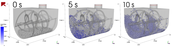
A liquid bridge is formed when two particles with liquid films get close enough for their films to touch, or "bridge". This is a type of adhesion model that can be useful when studying wet particulate processes. An example from such a process is provided in Figure 20.1: Example mixing process using the Liquid Bridge Model, where liquid from a wet additive (blue) is transferred to a dry power (white) over time.
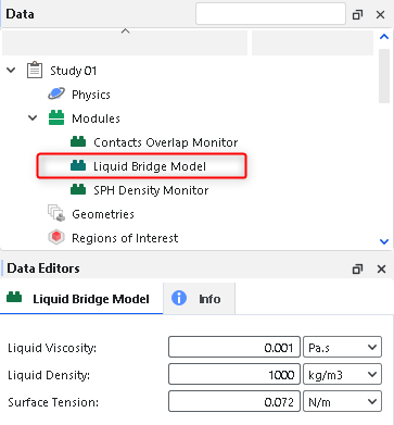
If you want to include the effect of liquid films around particles in the simulation, you can choose to enable the Liquid Bridge Model module (Figure 20.2: Liquid Bridge Model module options.) prior to processing your simulation.
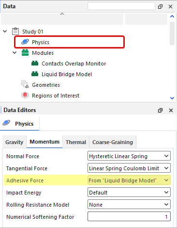
Enabling the Liquid Bridge Model module overrides the Adhesive Force model that is defined on the Physics | Momentum tab, as shown in Figure 20.3: Liquid Bridge Model overriding the Adhesive Force setting..
During processing, Rocky applies a liquid film that forms around each particle, and predicts when particles get close enough to each other (or to a boundary) to form a liquid bridge. When liquid bridges are formed, Rocky then calculates the capillary and viscous forces that the bridges exert over the particles and as the simulation progresses, calculates the redistribution of liquid mass between the particles.
Only particles in Rocky are considered to have liquid films associated with them. However, it is still possible for a particle to create a liquid bridge with a boundary. In these cases, only the particle contributes liquid to the bridge's formation, and liquid bridge forces are considered when computing the interaction between particles and boundaries.
Note: The liquid mass is not included in the particle mass when solving motion equations for the particle. For example, if a dry particle has 0.1 kg and the liquid film around it has 0.001 kg, the motion equations for the particle will be solved considering only a mass of 0.1 kg.
Use Figure 20.2: Liquid Bridge Model module options. above and the parameter definitions below to understand how to enable and configure the Liquid Bridge Model.
Liquid Viscosity: This defines the viscosity of the liquid film around particles.
Range: [Positive values]
The default value of 0.001 Pa.s is equal to the viscosity of water.
Liquid Density: This defines the density of the liquid film around particles.
Range: [Positive values]
The default value of 1000 kg/m3 is equal to the density of water
Surface Tension: This defines the surface tension of the liquid film around particles.
Range: [Positive values]
The default value of 0.072 N/m is equal to the surface tension of water.
In addition to the module itself, there will be other places within the Rocky UI where additional Liquid Bridge Model parameters will be available, including:
Materials Interactions
Inlets and Outlets
The additional options on the Materials Interaction tab (Figure 20.4: Liquid Bridge Model Materials Interactions options.) help you define how the liquid bridge will act when it is formed between particles, or between particles and boundaries.
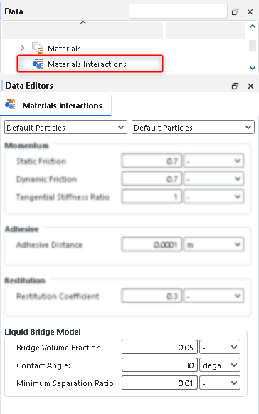
These parameters are explained below:
Bridge Volume Fraction: This defines the fraction of the liquid bridge volume that the particle pair will each contribute to when they are close enough for their liquid films to form a bridge. Each particle will contribute to the bridge with a liquid volume equal to the Bridge Volume Fraction times the volume of the film around it. For particle-to-boundary interaction pairs, only the particle liquid contributes to the formation of the bridge.
Range: [0-1]
The recommended range is 0.05 - 0.10
Contact Angle: This defines the angle between the surface of the liquid bridge and the particle (and/or boundary) surfaces between which it formed. It is used to compute the critical rupture distance for the liquid bridge between particles, and is also used to calculate the capillary force.
Range: [Greater than zero but less than 90]
Minimum Separation Ratio: This defines the smallest (minimum) separation distance below which the capillary and viscous liquid bridge forces will remain with a constant value, which is computed using the minimum distance. The minimum separation distance is obtained by multiplying the Min. Separation Ratio and the radius of the bigger particle of the pair (or just the radius of the particle when it is a particle-boundary interaction). Above this separation distance, the liquid bridge force is computed using the real separation values. This numerical artifact was implemented to avoid extremely high values when the separation is close to zero.
Range: [Values above zero]
For Particle Inlet and Volumetric Inlet, a new Modules sub-tab will appear showing a row for each particle group to help you define the liquid film input properties of the particles, as shown in Figure 20.5: Options for a Volumetric Inlet (left) and a Particle Inlet (right).
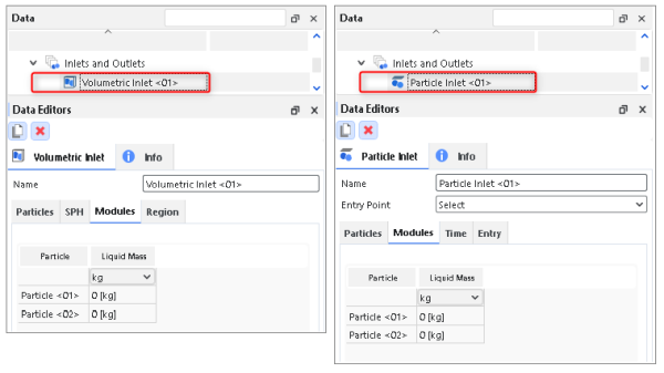
Within the table on the Modules sub-tab, one parameter (column) can be set per Particle Group (row), as defined below:
Particle: For each row, lists the Particle Group that is defined on the Particles sub-tab.
Range: [Automatically provided]
Liquid Mass: This defines the liquid mass that will be applied to each particle within the selected Particle Group when it enters into the simulation. Important: Every particle in the set, regardless of the particle size or volume, will contain the same amount of liquid mass when it enters into the simulation.
Range: [Values zero or greater]
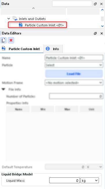
For Particle Custom Inlets, a new Liquid Bridge Model section will appear to help you define the liquid film input properties of the particles, as shown in Figure 20.6: Options for a Particle Custom Inlet.. The only parameter in this section is Liquid Mass, which is defined exactly the same as indicated in the preceding section.
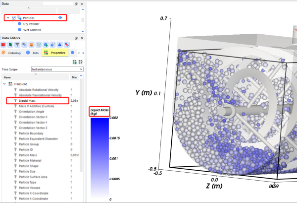
After processing the simulation, a new Liquid Mass property will be available for the main Particles entity (Figure 20.7: Options for a Particle Custom Inlet.), which provides the mass of the liquid film around a particle. This can help you to visualize the evolution of the particle's liquid content, as the liquid can be transferred from particle to particle during each collision.
You can choose to analyze this property in a plot or histogram window.
Or, you can choose to display this property graphically in a 3D View window.
Note: Properties generated by this module will only appear if the Upscaling is disabled.Refer to Rocky User Manual (5.1.7. About Meshed Particles Upscaling) for more details.
Ensure that the module is enabled. (From the Data panel, select Modules and then from the Data Editors panel, ensure the Liquid Bridge Model checkbox is enabled.)
From the Data panel, under Modules, select the new Liquid Bridge Model entry.
From the Data Editors panel, on the Liquid Bridge Model tab, enter the values you want.
Continue setting up the simulation as you normally would, with the following exceptions:
When setting up your Materials Interactions, be sure to define the Liquid Bridge Model values you want for each material interaction pair.
When setting up your Inlets and Outlets, be sure to define the parameters on the Modules tab (for Particle Inlet and Volumetric Inlet) or in the Liquid Bridge Model section (for Particle Custom Inlets).
Process the simulation as you normally would.
When you are ready to post-process your simulation results, you can make use of the new parameter on the Properties tab for the main Particles entity
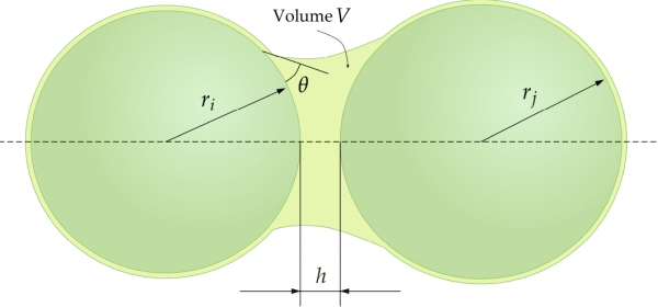
The Liquid Bridge Model module in Rocky calculates capillary and viscous forces acting over particles due the presence of interstitial liquid bridges. A liquid bridge is formed when wet particles become closer to each other or to a boundary, as depicted schematically in Figures Figure 20.8: Geometry of a liquid bridge between two particles. and Figure 20.9: Geometry of a liquid bridge between a particle and a boundary., respectively.
A liquid bridge exerts an attractive capillary force over the particles, which is calculated in Rocky according to a correlation derived by Mikami et al.[15]. For a bridge between two particles, the magnitude of this force is given by the expression:
 | (20–1) |
In this expression,  is the surface tension,
  is the geometric mean of the radio of the two bridged particles, and
 is the dimensionless separation distance between the particles.
Additionally, A, B and C are
coefficients that depend on the dimensionless volume of the liquid bridge,
is the dimensionless separation distance between the particles.
Additionally, A, B and C are
coefficients that depend on the dimensionless volume of the liquid bridge,  and the contact angle,
  , through the following expressions:
 | (20–2) |
 | (20–3) |
 | (20–4) |
The dimensionless parameters included in the expressions above are defined as follows:
 | (20–5) |
 | (20–6) |
where  is the separation distance between the bridged particles, as depicted in
Figure 20.9: Geometry of a liquid bridge between a particle and a
boundary., and
is the separation distance between the bridged particles, as depicted in
Figure 20.9: Geometry of a liquid bridge between a particle and a
boundary., and  is the volume of the liquid contained in the bridge. Moreover,
  is defined as:
 | (20–7) |
where  and
and  are the radii of the two bridged particles. For non-spherical particles, the
radius of each particle is taken one half of its sieve size.
are the radii of the two bridged particles. For non-spherical particles, the
radius of each particle is taken one half of its sieve size.
The volume of the liquid bridge is calculated as:
 | (20–8) |
where  and
and  are the volumes of the liquid films around the two particles, respectively,
defined as:
are the volumes of the liquid films around the two particles, respectively,
defined as:
 | (20–9) |
 | (20–10) |
where  and
and  are the liquid masses and
  and
and  are the densities of the liquid films around the two particles,
respectively.
are the densities of the liquid films around the two particles,
respectively.
Additionally,  is a user-defined parameter listed as Bridge Volume
Fraction in the Materials Interactions section of the Rocky
UI.
is a user-defined parameter listed as Bridge Volume
Fraction in the Materials Interactions section of the Rocky
UI.
Mikami et al.[15] also provide expressions for the coefficients in Equation 20–1 corresponding to a liquid bridge between a particle and a boundary, as the one depicted in Figure 20.9: Geometry of a liquid bridge between a particle and a boundary.. Those expressions are the following:
 | (20–11) |
 | (20–12) |
 | (20–13) |
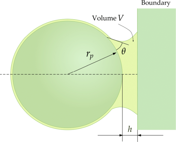
In this specific case, both  and
and  will be equal to the radius of the particle interacting with the boundary,
  . In the current Liquid Bridge Model in Rocky, boundaries do not have
associated a liquid film. Therefore, in particle-boundary bridges only particles will
contribute with liquid to the formation of the bridge. This means that the bridge volume in
those cases will be given by:
. In the current Liquid Bridge Model in Rocky, boundaries do not have
associated a liquid film. Therefore, in particle-boundary bridges only particles will
contribute with liquid to the formation of the bridge. This means that the bridge volume in
those cases will be given by:
 | (20–14) |
where  is the volume of the liquid film around the particle in a particle-boundary
bridge interaction.
is the volume of the liquid film around the particle in a particle-boundary
bridge interaction.
In Rocky, the amount of liquid carried by each particle is tracked though a special particle property called Liquid Mass. This property can be visualized and post-processed after a simulation has been completed. Additionally, users can specify the value of the initial mass of liquid carried by the particles when they enter to the domain. At any given time during the simulation, the volumes of the liquid films that appear on equations Equation 20–7 and Equation 20–14 will be computed using the liquid mass of each particle and the liquid density, which is a property that users must specify.
The mass of the liquid films attached to particles can vary throughout a simulation because it can be redistributed when a bridge interaction between particles ends. The liquid redistribution scheme implemented in Rocky is quite simple. When a liquid bridge between two particles is broken, half of the mass of liquid that was contained in the bridge is added to the liquid mass associated to each particle. On the other hand, when a particle-boundary bridge is ruptured, all the liquid mass goes to the particle, since boundaries are not able to retain liquid films in the current model implemented in Rocky.
The criterion for the rupture of a liquid bridge is based only on the value of the
separation distance,  . When that distance exceeds a critical value
  , the liquid bridge will break and, therefore, the bridge interaction will
finish. Rocky uses the following expressions for the dimensionless critical distance, provided
by Mikami et al.[15]:
, the liquid bridge will break and, therefore, the bridge interaction will
finish. Rocky uses the following expressions for the dimensionless critical distance, provided
by Mikami et al.[15]:
 | (20–15) |
for particle-to-particle liquid bridges, and
 | (20–16) |
for particle-to-boundary liquid bridges.
In addition to capillary forces, the Liquid Bridge Model in Rocky includes viscous forces that oppose the relative motion between particles or between a particle and a boundary, joined by a bridge. The expressions used for those viscous forces, derived from the lubrication theory, are taken from Nase et al. [16]. Unlike the capillary force that acts always in the normal direction, the viscous forces have a normal component and a tangential component. The expressions for those components are, respectively:
 | (20–17) |
 | (20–18) |
where:
 is the liquid absolute viscosity.
 Values of fluid properties, such as viscosity and density, as well as other properties such as surface tension and contact angle, must be specified by users through the Rocky UI.
 is the equivalent radius, defined as:
(20–19)
 and
and  are the normal and tangential components of the relative velocity, in
relation to the mid plane between the two particles or the particle and the boundary.
are the normal and tangential components of the relative velocity, in
relation to the mid plane between the two particles or the particle and the boundary.  is the dimensionless equivalent radius, defined as:
(20–20)
The minus sign in equations Equation 20–17 and Equation 20–18 indicates that the viscous forces always oppose to the relative motion, as already mentioned. As a consequence, the normal viscous force will behave as a repulsive force when particles approach each other, and as an attractive force when they move away.
As the separation distance  decreases to zero, both components of the viscous force tend to infinity. In
order to avoid stability issues caused by very large forces, Rocky uses a cut-off value for
the separation distance. This cut-off value is determined by an input parameter listed in the
Rocky UI as Minimum Separation Ratio. So, if
decreases to zero, both components of the viscous force tend to infinity. In
order to avoid stability issues caused by very large forces, Rocky uses a cut-off value for
the separation distance. This cut-off value is determined by an input parameter listed in the
Rocky UI as Minimum Separation Ratio. So, if  is the value of this parameter, the cut-off value for the separation
distance will be given by:
is the value of this parameter, the cut-off value for the separation
distance will be given by:
 | (20–21) |
Whenever a separation distance in a liquid bridge falls below  , this latter value will be used in equations Equation 20–19 and Equation 20–5 instead of the actual value,
  .
.
In Rocky, the CGM is a scaling force for contact forces, attractive or repulsive, is quadric.
 | (20–22) |
Where  is the CGM scale factor,
  the original contact force, and
  is the CGM scaled force.
A liquid bridge exerts an attractive capillary force over the particles, which is calculated in Rocky according to a correlation derived by Mikami et al. For a bridge between two particles, the magnitude of this force is given by the expression:
 | (20–23) |
In this expression, is the surface tension,
  the geometric meanof the radii of the two bridged particles, and
 is the dimensionless separationdistance between the particles.
Additionally,A,B and C are coefficients thatdepend
on the dimensionless volume of the liquid bridge,
is the dimensionless separationdistance between the particles.
Additionally,A,B and C are coefficients thatdepend
on the dimensionless volume of the liquid bridge,  and the contactangle,
  through the following expressions:
 | (20–24) |
The dimensionless parameters included in the expressions above are defined as follows:
 | (20–25) |
Where  is the volume of the liquid contained in the bridge. Moreover,
 is defined as:
 | (20–26) |
Where  and
and  are the radii of the two bridged particles. For non-spherical particles, the
radius of each particle is taken one-half of its sieve size.
are the radii of the two bridged particles. For non-spherical particles, the
radius of each particle is taken one-half of its sieve size.
Once the CGM radius is scaled by  , if one scales the
  by
by  the constant A,B, and C are equal
to the original particle without scaling.
the constant A,B, and C are equal
to the original particle without scaling.
Finally, if one multiple the surface tension  by the
  , one gets the CGM Force as:
 | (20–27) |
Therefore, in order to make the Liquid Bridge Model compatible with CGM one just needs to
cubic scale the volume of liquid bridge  , and scale the surface tension by the
  factor.