


Hairpin Winding
Note: Not available for Axial Flux machines.
Hairpin windings have the following advantages over mush wound windings:
- automation of the winding process
- improved cooling winding. The exposed endwindings can be better cooled than the large bundles of conductors in mush wound machines.
The disadvantage of hairpin windings is that AC winding losses can be larger due to the larger conductor sizes.
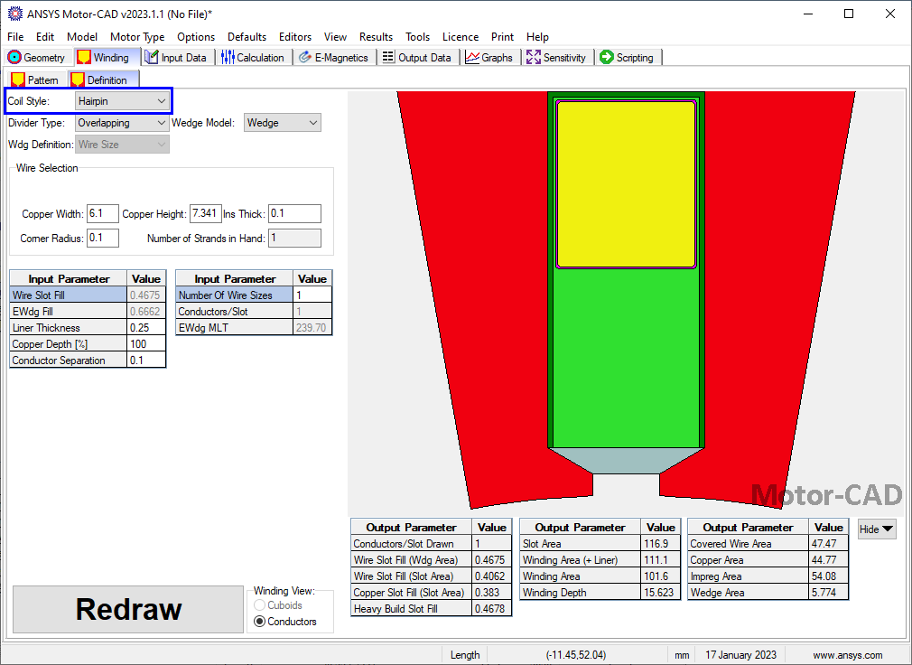
Hairpin windings can be set from the coil style option on the Winding Definition Page.
Winding Pattern
Hairpin wound machines are typically wound using a wave winding pattern. To model the wave winding pattern in Motor-CAD use the Wave or Custom winding pattern (see Hairpin Winding Patterns for details).
End Windings
The end winding lengths and surface areas at each end of the stack are calculated using the pattern definition and the geometry of the slots and conductors. See Hairpin End Winding Length Calculation.
The lengths allow accurate calculation of losses and distribution of losses across cuboids in the thermal model.
Surface areas of the hairpin end windings are calculated allowing the cooling of each surface to be considered separately. See Hairpin Thermal Model.
Losses
The loss dissipated in each layer is scaled proportionally with the length of the conductors in the layer.
See also: Winding Pattern, Winding Definition Page, Coil Style, Hairpin End Winding Length Calculation,