


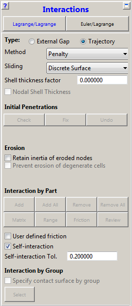
- Interaction Trajectory (Trajectory options)
The Trajectory contact algorithm is implemented for all unstructured Lagrangian solvers and SPH.
- Method
Method in which a contacting node is pushed back to the true contact position during the computational cycle.
There are three methods available:
- None
No contact defined.
- Penalty
If a contact event is detected, a local penalty force is calculated to push the node back to the face. Equal and opposite forces are calculated on the nodes of the face in order to conserve linear and angular momentum. The applied penalty force will push the node back towards the true contact position during the cycle. However, it will take several cycles to satisfy the contact condition. Kinetic energy is not necessarily conserved. The conservation of energy can be tracked using the energy time history.
- Decomposition Response (DCR)
All contacts that take place at the same point in time are first detected. The response of the system to these contact events is then calculated to conserve momentum and energy. During this process, forces are calculated to ensure that the resulting position of the nodes and faces does not result in further penetration at that point in time. The decomposition response algorithm is more impulsive (in a given computational cycle) than the penalty method. This can give rise to large hourglass energies and energy errors.
- Sliding
The algorithm used to determine how a node in contact slides along a surface. When a node that is in contact slides to the edge of a face on a mesh, the next face that the node slides on can be determined using two methods:
- Discrete Surface
This is the default option. The next face that the contact node slides on is determined using the contact detection algorithm.
- Connected Surface
The next face that the contact node slides on is determined using the mesh connectivity.
The Discrete Surface option will provide the most time efficient solution, but penetrations of nodes may be seen in situations where the faces that the nodes are sliding on are experiencing large deformations or rotations. When such penetrations occur, it is recommended the user switches to the Connected Surface option.
- Shell thickness factor
The value of the factor must be between 0.0 and 1.0, and determines the amount of the shell thickness that is taken into account for the interaction distance. Typically, a value of 0.0 or 1.0 should be chosen.
Interaction in the solver is always taking place between a node and a face (contact surface). You can enable two (complementary) algorithms to take the shell thickness into account:
Shell thickness for the faces which will offset the faces
Shell thickness for the nodes which creates a "sphere" around the node
In order to use one or both of these thickness algorithms you can:
Set the Shell thickness factor to a value other than zero to activate the Shell thickness algorithm for the faces
Enable Nodal Shell Thickness to activate the Shell thickness algorithm for the nodes, in addition to Shell thickness for the faces
Interaction Behavior with Shell Thickness
Setting the factor to a value other than zero means that the contact surface is positioned at (0.5 x shell thickness x factor) on both sides of the shell mid plane.
A factor of 0.0 means that the shell has no contact thickness and the contact surface is positioned at the shell mid plane. Note that with this setting the nodal shell thickness can not be activated separately.
The contact area of a node depends on the setting for Nodal Shell Thickness. If it is disabled, the node is always located at the mid-surface of the shell (Situation I). If it is enabled the node is located at a spherical distance of half the thickness away from the physical node location (Situation II).
Two shell parts with thickness δ1 and δ2 will not contact at a distance of (δ1/2 + δ2/2), but at a distance which is half of the largest shell thickness as is depicted below.

Note that for shell node on solid face impacts, the node will be able to get to within zero distance of the solid face; the thickness for the shell nodes will not be taken into account. The solid nodes will, however, find the shell faces at contact distance.
By enabling the nodal shell thickness, two shell parts will contact at a distance of (δ1/2 + δ2/2). From a physical point of view this is correct, as can be seen in the picture below.

Note that care should be taken for nodes that are on or close to a free edge of the shell surface because the node may find contact in an unexpected manner due to the spherical contact around these nodes. This is shown below in a 2D manner, where for example node 1 and 2 have an additional contact area which extends beyond the geometry.

- Initial Penetrations
- Check
On clicking this button, Autodyn will search the model for initial penetrations of nodes into surfaces. If any penetrating nodes/surfaces are found, a new Group will be created so that they can be identified/displayed using the Groups panel. Nodes that initially penetrate surfaces will be "missed" by the contact algorithm.
- Fix
When this option is selected the initially penetrated nodes are set back to the closest contact surface and no initial penetrations are present at the start of the analysis.
This option is meant for situations where small initial penetrations occur (for example because of round-off) and should be used with care because the analysis model geometry is changed.
Note that it may not be possible to remove all initial penetrations with this algorithm. Features are available in the DesignModeler and Meshing application to prevent initial penetrations occurring.
- Undo
This option will restore the geometry of the analysis model before the initial penetrations were fixed.
It is recommended that the fixed initial penetrations are checked before the model is modified further otherwise it may not be possible to undo the last fix operation.
- Erosion
- Retain inertia of eroded nodes
Check this box if you want to retain the inertial of eroded nodes (otherwise eroded nodes are removed from the model).
- Interaction by Part
- Add
Sets interactions between Parts.
- Add All
Sets all Parts to interact with each other.
- Remove
Removes interactions between Parts.
- Remove All
Removes all interactions between Parts.
- Matrix
Sets interactions using a Part matrix.
- Range
Sets the index range of each Part that will be checked for interactions.
- Friction
Sets static friction coefficients between different Parts.
- Review
Enables a review of all of your interaction settings.
- User defined friction
Aside from the friction definition through the interaction by Part method described above there is also a user defined friction option available through the use of a user-subroutine called EXFRICTION.

- Self Interaction
If the self-interaction option is switched on the contact detection algorithm will also check for external nodes of a part contacting with faces of the same part in addition to other parts. This is the most robust contact setting since all possible external contacts should be detected.
- Self-interaction Tol.
The self-interaction option enables automatic erosion when an element deforms such that one of its nodes comes within a specified distance of one of its faces. This option will prevent volume elements becoming degenerate.
The specified distance is calculated using the Self-interaction Tol. value which is a factor in the range 0.1 to 0.5. This factor is multiplied by the smallest characteristic dimension of the elements in the mesh to give a physical dimension.

- Interaction by Group
In many calculations, the contact region may be relatively small in comparison to the entire model, and as the interactions calculation is numerically intensive, it would be beneficial if the scope of its work were limited to this smaller area. The Group Contact option enables you to select a set of face groups to describe the extent of the interactions in unstructured models.

Select the "Specify Group Contacts by Group" toggle and click Select, to open the "Select Groups to include in Contact" dialog, and use the Add/Remove button to specify which face groups are to be included in the contact calculations.

During execution, any faces eroded will be removed from the group, and any new faces uncovered will be added to a group named "Uncovered faces". Unstructured Beams and SPH can also be included as a node group to participate in contact.

Note: Note that Group Contact is additive to Part contact. Selecting a Part for contact results in all external faces in that Part being checked for contact. Group contact should be used to add additional external faces from Parts that have been excluded from contact in the Part interaction matrix.
Friction cannot be specified on a group-by-group basis. However, friction coefficients set on a part-by-part basis as described in the section on Interaction by Part will apply regardless of whether any interactions by part have been set.