
Introduction
This example looks at the scattering from a standard Radar Cross Section (RCS) test model (specifically, the ogive) using the HFSS design type with an IE region assigned to the ogive. An IE region results in a full-wave Integral Equation solver being used to analyze the model. This solver is particularly well suited for analyzing large conducting objects, and it eliminates the necessity of creating an open region (that is, a vacuum or air box) around the model to determine far field effects.
IE Regions in an HFSS design have replaced the legacy HFSS-IE design type. If you open a legacy HFSS-IE design, you are prompted with the option to automatically convert the model to an HFSS design with an IE Region applied to its objects.
You will perform the following tasks to complete this exercise:
- Create a new project, insert an HFSS design, and set the solution type
- Enable Legacy View Orientations
- Create the ogive by drawing a segmented equation based curve and sweeping it in specified increments around the X-axis
- Define an incident plane wave
- Assign an IE region
- Add the solution setup
- Run the simulation
- Overlay and animate the surface current magnitudes
- Plot the monostatic RCS results
RCS Test Model (Ogive)
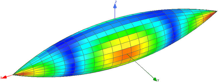
We will look at the scattering from a conducting ogive with a length of 10" and a half angle of 22.6° (0.3948 radians). The ogive lies with its axis along the global X axis. The equation that defines this model is:
F(x) = √ {1 - [x/5 * sin(22.6°)]2} - cos(22.6°)
y = F(x) * cos(φ) / [1 - cos(22.6°)]
z = F(x) * sin(φ) / [1 - cos(22.6°)]
For this exercise, x, y, and z are defined in inches.