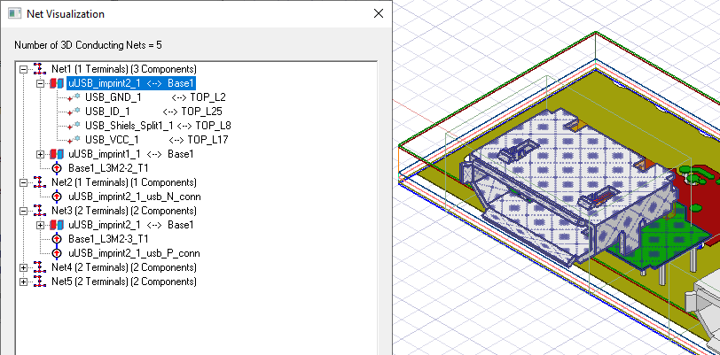
Show Nets for DC Continuity for 3D Conductors
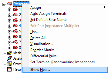
The Show Nets
command appears in the HFSS>Excitations
menu and by right-clicking on Excitations
in the Project tree.
Selecting Show Nets... displays the Net Visualization dialog that lists the nets and associated terminals. You can use the dialog to select any net or terminal. You can continue to work in the Modeler window with the dialog open.
For a net to appear in the Net Visualization dialog box, the conductivity of the assigned material must be equal to or greater than 20,000 siemens/m, or the Resistance must be less than 3.142 ohms. Conductivity is set by material assignment (in the 3D Modeler window or a boundary condition), and Resistance is set by boundary conditions (e.g., Impedance or LumpedRLC).
In the Net Visualization dialog, you can sort the nets in ascending or descending order, relative to the number of terminals. This helps you locate GND nets, which have no terminals.
Text at the top of list box provides the total number 3D Conducting nets. Naming of nets is automatic and follows the convention: "Net1 (0 Terminals)", "Net2 (1 Terminals)"…"Net<N> (<T> Terminals)". Net Names are not editable.
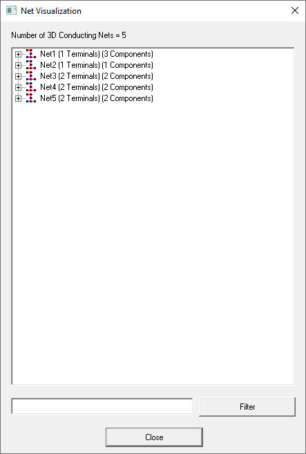
For designs with many nets, you can enter text and wild cards in the field, and click the Filter button.
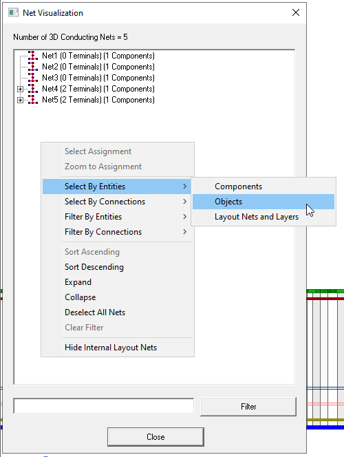
Right-click in the Net Visualization dialog to view the short-cut menu. The menu is context sensitive, depending on whether you click on a particular net object, or in the white area.
-
Select assignment: If you right-click over selection in the tree, selects entities present in the selection. If the right click menu is invoked on the surrounding blank space, this menu item is disabled as there is no selection.
-
Zoom to assignment: If you right click over a selection in the tree, zooms to the entities present in the selection. If you right click menu on the surrounding blank space, this menu item is disabled as there is no selection.
-
Select by entities: If you right invokes a dialog containing object, component, or net and layer names present in the selection if the right click menu is invoked over some selection in the tree. If the right click menu is invoked on the surrounding blank space, all object or component names present in the project are displayed. Selecting one or multiple of these object or component names selects all the nets which contain any of the selected entities.
-
Select by connections: If you right click over some selection in the tree this produces a dialog containing object or component names present in the selection . If you right click menu on the surrounding blank space, a dialog with all object or component names present in the project displays. Selecting a pair of these object or component names selects all the nets which contain this pair of entities, signifying a direct or indirect connection between these entities.
-
Filter by entities: A new dialog is invoked containing object, component, or net and layer names present in the selection if the right click menu is invoked over some selection in the tree. If the right click menu is invoked on the surrounding blank space, all object or component names present in the project are displayed. Selecting one or multiple of these object or component names filters all the nets which contain any of the selected entities.
-
Filter by connections: A new dialog is invoked containing object or component names present in the selection if the right click menu is invoked over some selection in the tree. If the right click menu is invoked on the surrounding blank space, all object or component names present in the project are displayed. Selecting a pair of these object or component names filters all the nets which contain this pair of entities, signifying a direct or indirect connection between these entities.
-
Sort ascending: Sorts the nets in ascending order of their names.
-
Sort descending: Sorts the nets in descending order of their names.
-
Expand: Expands the selection in the tree if the right click menu is invoked over some selection in the tree. If the right click menu is invoked on the surrounding blank space, menu item expands all the nets.
-
Collapse: Collapses the selection in the tree if the right click menu is invoked over some selection in the tree. If the right click menu is invoked on the surrounding blank space, menu item collapses all the nets.
-
Deselect All Nets: Deselects all the entities present in the project. Clears the selection of all the previously selected entities.
-
Clear Filter: Clears all the filtering applied on nets and shows all the nets.
-
Hide internal layout nets: Hides all the nets which are internal to layout component
Along with the “filter by entities” and the “filter by connections” menu items, you can also filter nets using text input. The text box for this functionality is shown below:

Features of this text box are:
-
It accepts one or more object or component names.
-
Multiple entries can be entered by separating them with comma operator (“,”).
-
Entity connections can be entered by separating entity names with dash operator (“-”).
-
Wild cards “*” and “&” can be applied. For example, LayoutComp1 and HfssComp2 can both be represented simultaneously as “*Comp*”.
Similarly, LayoutComp1 and LayoutComp2 can be represented simultaneously as “LayoutComp&”. For example, (Box1, Box2, Comp1 – Comp2): This string applies filter based on if a net contains Box1, or Box2, or connection between Comp1 and Comp2.
-
Selected nets/components are highlighted in the Modeler window.