
Set Mode Polarity Using Integration Line
By drawing integration lines you can set mode polarity. The settings in the General tab of the Wave Port dialog box for a single mode and the integration line drawn for a WR-90 rectangular waveguide are shown below.
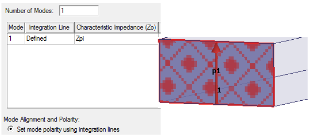
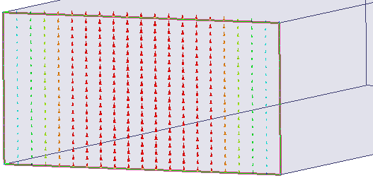
The mode alignment can also be set using the integration lines. In this case the direction is flipped upward as set by the direction of the integration line.
.
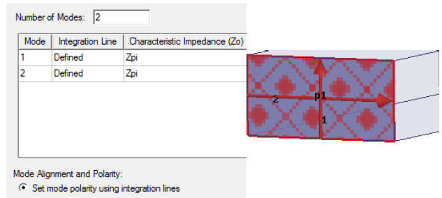
See the settings for another WR-90 waveguide with the integration lines 1 and 2 defined for two modes.
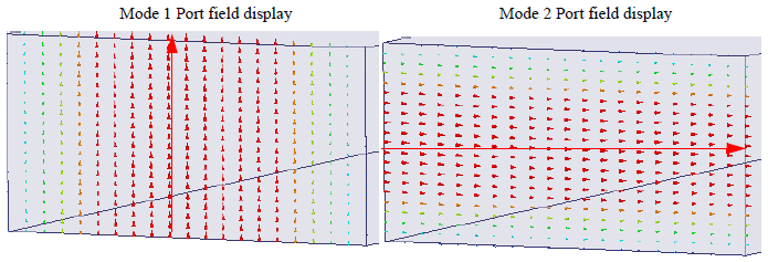
The corresponding port field display are as follows:
Note:
The voltage along integration line 1 is positive for Mode 1 and the voltage along the integration line 2 is positive for Mode 2.