Modes with Default Settings
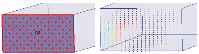
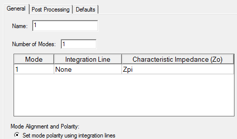
The following figure shows a wave port assigned on the face of a rectangular waveguide. The default settings in the General tab of the Wave Port dialog box are used and the port is named p1. No integration line has been defined. From the Project Tree if you select the option Mode1 under Port Field Display you can see the electric field patterns for that mode. The direction of mode propagation for the corresponding wave port is shown below. Notice that the intensity is highest in the middle (indicated by the red arrows) and tapers to zero on the sides for the TE01 mode for the rectangular waveguide. Since no integration line has been defined, the polarity is arbitrarily up or down.