
Material Tensors Applied at PML Boundaries
PMLs materials are complex anisotropic. An example is shown below.
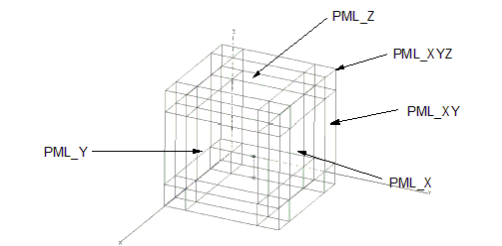
To ensure that there will not be any reflection at the PML/air interface, the bi-axial diagonal material tensors for x-, y- and z-directed PMLs (PML_X, PML_Y, and PML_Z) are as follows.
For PML_X:
| 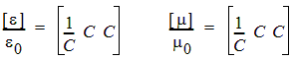 | (1) |
For PML_Y:
| 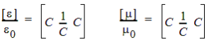 | (2) |
For PML_Z:
| 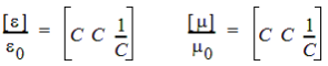 | (3) |
where C = a - jb.
The tensors designated as PML_X characterize an x-directed PML corresponding to a PML wall in the yz plane. Similarly, PML_Y and PML_Z are designated tensors for y- and z-directed PMLs.
PMLs of different directions must be joined in order to construct a box with PML walls. To ensure complete coverage where the edges and corners of two PMLs meet, create edge and corner PML objects. The tensors of an edge object joining PML_X and PML_Y are as follows for PML_XY:
|  | (4) |
A similar tensor construction rule is valid for joining x- and z-directed and y- and z-directed PMLs. The tensor for a corner object is a follows for PML_XYZ:
|  | (5) |
This example in shows the material in GLOBAL coordinate system, while the Material Manager shows the materials in LOCAL coordinate system assigned to the object, which are then rotated to the global coordinate system by the solver.