
Lumped RLC Boundaries
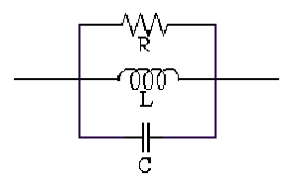
To model any combination of lumped resistor, inductor, and/or capacitor in parallel on a surface, create a lumped RLC boundary. A lumped RLC boundary represents R, L, and C in parallel:
Similar to impedance boundaries, the following condition holds at lumped RLC boundaries:

Unlike impedance boundaries, you are not required to supply the impedance per square, but you must supply the actual values for R, L, and C. HFSS then determines the impedance per square of the lumped RLC boundary at any frequency.
A Fast frequency sweep is supported for this boundary condition.