
HFSS-EMA3D Datalink Toolkit
Ansys EMA3D is a simulation tool for installed antenna patterns, including near fields and antenna coupling on electrically large platforms. EMA3D can import antenna data from HFSS to drive an SBR+ (Shooting and Bouncing Ray) simulation.
The HFSS-EMA3D ACT Toolkit exports antenna geometry, near-field and far-field representation from HFSS. A directory is created so that it can be imported to EMA3D.
The ACT Extensions window and the design wizards it contains (5G Wizard, HFSS Antenna Design Toolkit, HFSS-EMA3D Link, and Maxwell Eccentricities) are only available for the Windows version of the Ansys Electronics Desktop software. These items are not available when the software is installed on a Linux platform.
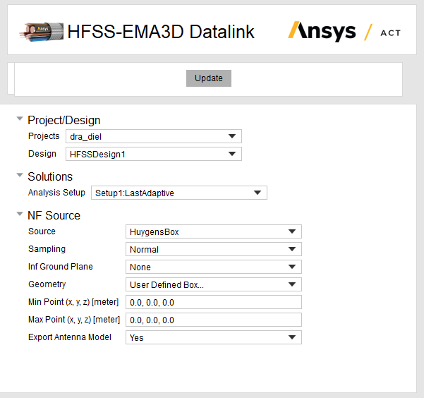
To load the HFSS-EMA3D toolkit:
- Use the View>ACT Extensions command to open the Wizard window for toolkit extensions implemented via Ansys ACT.
- Click on the Wizards box to load the available toolkits.
- Load the extension. This can be done with a right-click the newly added square and later selecting the Load Extension option.
- Return to the main menu by clicking on the back arrow.
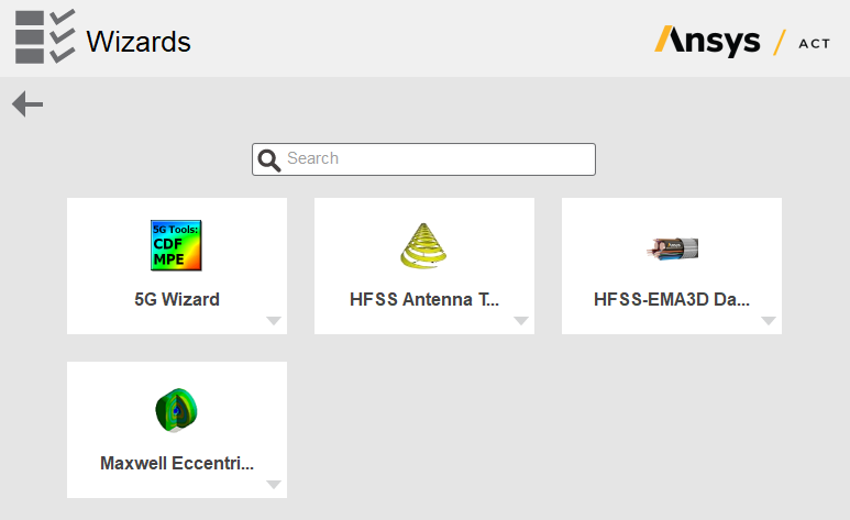
To use the HFSS-EMA3D toolkit:
- Create or open an antenna project with one or more HFSS designs.
- Analyze the project in HFSS and Save the results.
- To Export the sample project, open the wizards extension panel by clicking on View>ACT Extensions if not opened already.
-
Select the Wizards square from the extension panel. This will open a window with the loaded extensions. Select the HFSS-EMA3D Datalink tookit button.
-
The tookit menu will appear in the Wizards panel:
Project/Design
Project: Select the project. The projects currently open in Desktop are available for selection. The list of projects can be updated by clicking the Update button.
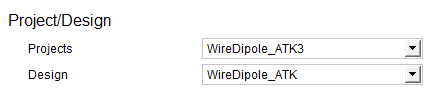
Select the design. Choose from the designs within the selected project.
Solutions: Selects the analysis setup to export from the different analysis setups available in the selected Project/Design. Only one analysis can be exported at a time.

NF Source:
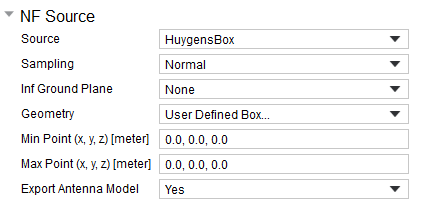
This section defines the geometry for the exported near-field data necessary to reconstruct the antenna in EMA3D. The toolkit exports the E and H fields on radiating surfaces or the faces of the Huygens Box based on user selection.
Source: Defines the source surfaces where E and H fields can be exported. There are two available options: RadiationSurfaces and HuygensBox. When you select RadiationSurfaces, HFSS exports E and H fields on Radiation boundaries, PML and FE-BI. When you select HuygensBox, the box should be placed close to the antenna, an offset of a λ/10 from the maximum dimensions of the antenna is recommended but larger offsets will work as well. The sample fields should be at least 8 points per wavelength ppw) on each face of the box. The HuygensBox option is not applicable when the design has a finite array.
If you choose to export on Radiation Surfaces, the only other options for NF Source are Sampling and whether to Export Antenna Model. Geometry and Infinite ground plane selection do not appear. If you have defined an Infinite ground plane, it will be directly taken from the boundary definition.
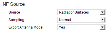
HFSS provides the actual geometry for one cell for array problem, so export antenna model option will only export the geometry for one cell. HFSS has the mesh exported for radiating surface which could gives an overall outline of the array but not details about every single cell. The antenna CAD model in EMA3D is used for display and placement purpose, to the current on radiation surface achieves similar functionality.
If you select Huygens Box the toolkit exports the E and H fields on the faces of the Huygens Box described in this section. The toolkit offers a menu with a calculated Region or User Defined Box.... The Huygens Box should be placed close to the antenna, an offset of a λ/10 from the maximum dimensions of the antenna is recommended but larger offsets will work as well. The sample fields should be at least 8 points per wavelength (ppw) on each face of the box.
Sampling: Defines the configuration type for the number of samples/points per wavelength (ppw) and Field Sampling Density for faces from selected Source when applicable. The menu has three options: Quick, Normal and Custom. Quick sets the ppw to 8 and the field sample density to 4 respectively; Normal sets it to 16 and 8 respectively and Custom unveils two new property panels so the user can customize the value of the properties. Only Field Sampling Density is applicable when you select RadiationSurfaces as Source.

NF Sampling: Defines the number of samples/points per wavelength (ppw) for each face of the box. A value of at least 8 is required to produce a faithful result later in EMA3D. This property is only available when Sampling is set to Custom and Source is set to HuygensBox
Field Sampling Density: Defines the number of samples that will be set by EMA3D in the Antenna's property panel. A value of at least half as much as NF Sampling is required to produce a faithful result later in EMA3D. Visible only when you select Custom.
Inf Ground Plane: Exports the ground plane information for the selected face. When loaded into EMA3D, the antenna will present the ground plane information introduced in this toolkit. This is practical to avoid the integration of the EH field in the selected face which eases the computation of the current sources. This property is set automatically if the user picks a specific Geometry. You can change this value at any time.
Geometry: The HFSS-EMA3D Datalink Toolkit defines a region likely to represent the best space to define the Huygens Box. The unavailable Min Point and Max Point values apply to the Region in the Global Coordinate System. If you want to use a customized setting, then you can select the option User Defined Box ... to enable the Min and Max Point fields, starting with the dimensions of the default calculated region.
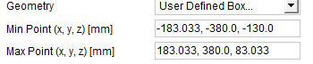
Min Point (x,y,z): The extension of the Huygen Box can be defined through two points with the maximum and minimum extensions of the box respectively. In this selector, the point with the minimum values of the box is entered. The value of the points is entered using 3 floating point numbers separated by a comma ','. The units of the numbers are shown in the panel descriptor. This property is set automatically if you pick a specific Geometry. You can change this value using the option User Defined Box ... in the Geometry selector.
Max Point (x,y,z): Defines the point with the maximum values of the box. The value of the points is entered using 3 floating point numbers separated by a comma ','. The units of the numbers are shown in the panel descriptor. This property is set automatically if the user picks an specific Geometry. You can change this value using the option User Defined Box ... in the Geometry selector.
Export Antenna Model: Specify whether to Export the Antenna Model to EMA3D.
Antenna Pattern Source: Infinite Sphere
Far-Field Setup: Selects the setup that will be used to export the far-field data from the toolkit. The options are populated from the specific project and design selected.
-
Set or change the Geometry value. Observe how the Huygens Box extensions change with the new geometry.
-
The tookit analyzes the different geometries present in the project. In most cases it is more convenient to define a box using the HFSS aids rather than writing them on entry.
-
Select Finish.
-
The export process begins when you press Finish. Once the process finishes, the HFSS-EMA3D datalink toolkit closes itself.
-
The exported project can be found on the same folder where the HFSS project is stored. This path will be used in the following step.
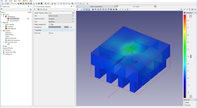
Note: If export data has been generated for multiple designs from the same
project, EMA3D will provide a dialog allowing the design of interest to be selected.