Example that Uses Near Field Links
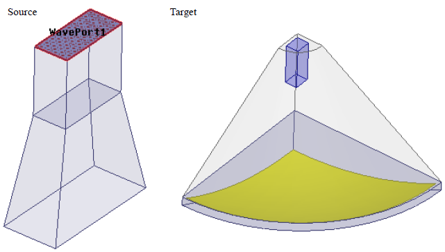
The following figure shows a horn antenna that will be dynamically linked to a target disk where the source will be included inside of the target.
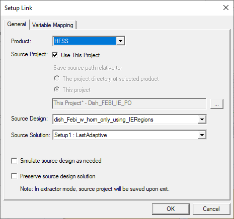
The Near Field Setup Link settings are as shown in the following figure.
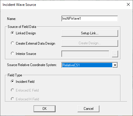
In the example of the horn antenna linking to a target dish, the co-ordinate systems of the source and the target coincide.
You
can use the Source Relative Coordinate System
menu to select the source co-ordinate system. For instance
if you want to move the source and its co-ordinate system closer to the
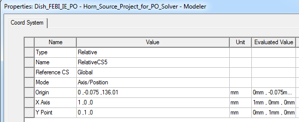
dish by 15 mm you can edit the Relative CS properties for the origin.
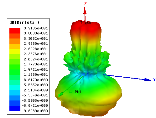
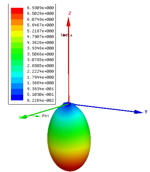
The 3D polar plot with the values of directivity for the source project (the standalone horn antenna without the dish) is shown below.
Then, when we apply the fields to the Target project with the dish, we get the values of the directivity shown in the following figure.
The standalone horn antenna without the dish radiates in the negative Z direction while the target project which includes the dish antenna, radiates in the positive Z-direction. The 3D polar plot with the values of directivity after the application of the Near Field link is shown in the following figure.