Example That Uses Far Field Links
This section describes linking an HFSS project to an HFSS-IE project while using the common feature of assigning Far Field Wave excitation.
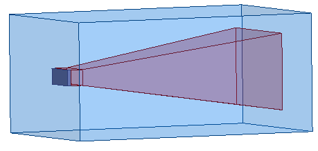
The horn antenna enclosed in an air box in the figure
below represents the source project designed in HFSS.
The
dish/reflector in the following figure is the target project designed in
HFSS-IE.
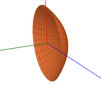
A
perfect E-boundary is assigned on the reflector.
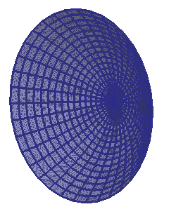
The
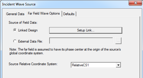
Far Field Wave Options panel has
the following settings.
From
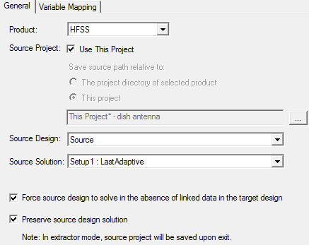
the Setup Link option, the fields are set as shown in the figure
to link the target to the source project (the horn antenna).
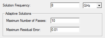
A
sample solution setup for this project is shown below:
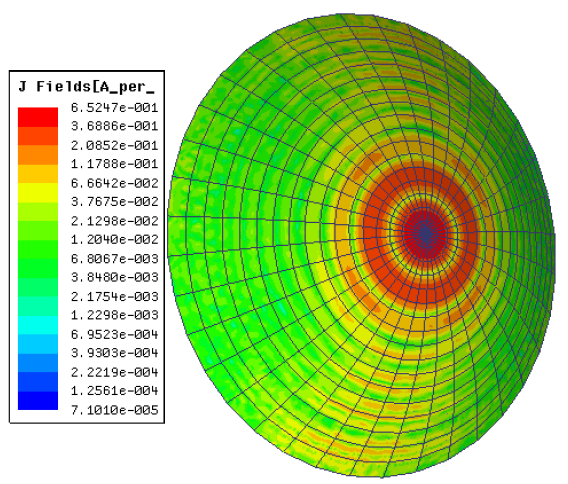
The resulting J Fields (magnetic fields) after solving the project are shown below.