
Cable Network
A Cable Network is linked field excitation used as part an overall cable solution implemented as dynamic data links between HFSS, 2D Extractor, and Circuit.
-
Each cable harness in HFSS is modeled as a single external field source based on quasi-static simulation of each cable cross-section in 2D Extractor and an analysis of the cable network in Circuit. The magnitude and distribution of the fields along each cable section is determined by the voltages and currents at the ends of each section, and then transmission line model is applied to propagate these fields along the cable length.

This HFSS design is a target of a new “Cable Field” coupled field datalink. The source of the datalink is the Circuit design that models the cable network. Each Cable Network will be treated as a single source and can be scaled at Edit Sources.To setup a Cable Network datalink, in the HFSS Modeler window, you select all 3D cable cables that are part of a network. Then click HFSS>Excitations>Assign>Linked Field>Cable Network... or right-click Excitations>Assign>Linked Field>Cable Network... This opens the Cable Network Setup dialog:
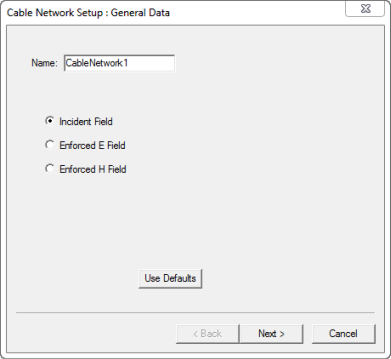
You have a field for the name, and selections for Incident Field, Enforced E Field, and Enforced H Field. -
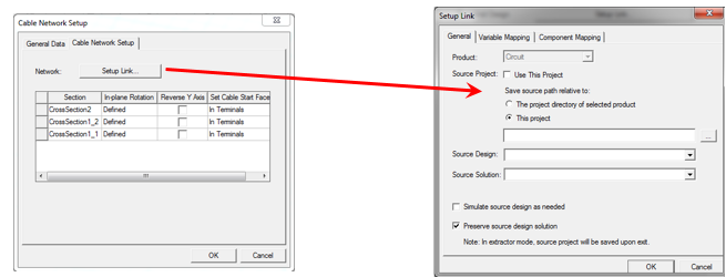
To specify the Circuit design, user can go to the second page and click the button “Setup Link…”. This displays the Setup Link dialog.
-
After specifying the source design, you switch to the Component Mapping tab to set up the mapping between each cable section in HFSS and a circuit component.
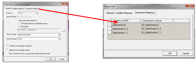
Click OK to exit the Setup Link dialog and complete the rest of the link setup in the Cable Network Source dialog.
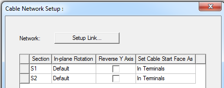
For each cable section, you need to specify:
-
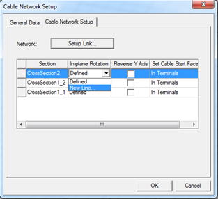
The In-plane rotation of the HFSS 3D section to the 2D Extractor cross-section by a direction line (which will be the local X axis of the cable cross-section face). The default is zero in-plane rotation, which is represented by a direction line originated at the starting point of the polyline and ended at the seam of the cable.
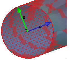
You can create new line or reverse the Y axis of the start cable cross-section face. -
The X and Y axis on both start and end faces are shown, which is useful when you want to align multiple cable orientations.
-
You map pins in Circuit to wires at ends of the cable in HFSS by specifying the starting end of the cable as “In Terminals” or “Out Terminals”. By default, the starting end of the cable is selected as the “In Terminals”. The “In” and “Out” faces are highlighted in the View window.
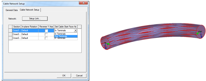
You can override the default selection by toggling the menu at the “Set Cable Start Face As” column.
-
Floating Cable/Linked Region
A Floating cable is defined as a cable object floating outside of FEM solution region. In order to define a floating cable, you need to define a linked region. A Linked region is used only for one-way link. We assume the source is inside the linked region, and the linked region only radiates to the field but does not have field scattered back to the region.
You can assign near/far field as well as a cable network to a linked region.
The Assign Linked Region menu item is in Assign Hybrid.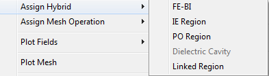
Linked region appears under “Hybrid Region” folder in project tree.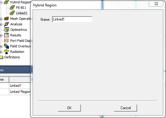
Cable Network Link Validation
- The number of 2D Extractor components in circuit should be equal to number of HFSS cable object
- For each cable object, the 2D cross-section center should match the center of the start face in local coordinate system.
- For each cable object, the 2D cross-section perimeter should match the perimeter of the start face.
- The cross-section should be perpendicular to the cable path in HFSS.