
Cable Modeling - Automotive Toolkit
To work with tool kits in the automotive industries:
- Click
- Enter a Name for the toolkit, and select Units.
- If you have a *.csv or *.tab file containing cable and outer jacket parameters, you can Import it.
- To manually modify the Cable Parameters:
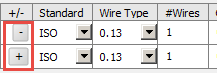
- Using the +/- column, add or remove wire types to create a bundle. Clicking the + button adds a new row. All rows but the initial row will have a - button to remove that row.
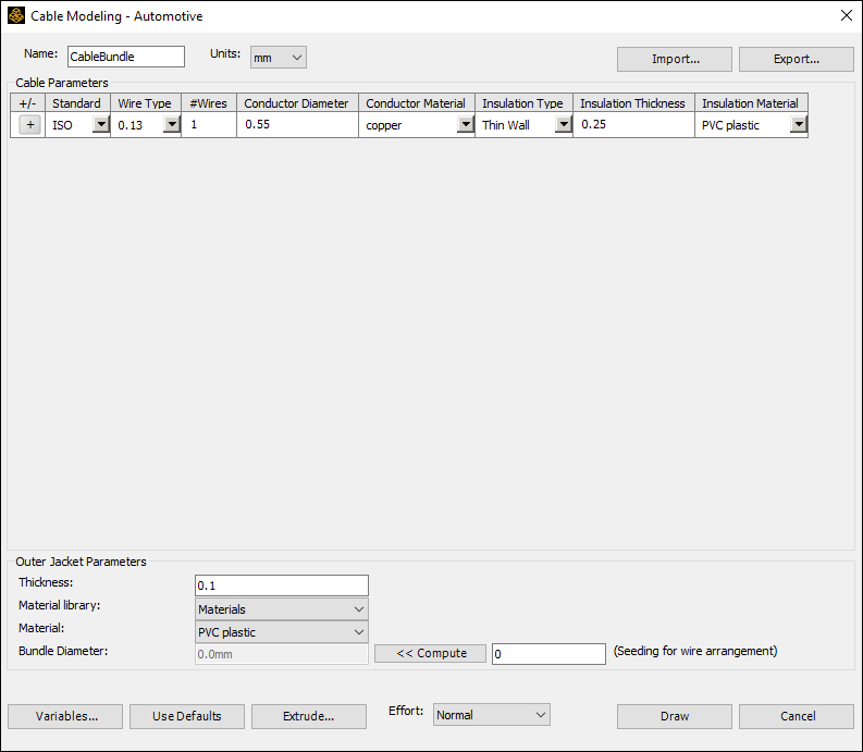
- In the Standard field, choose between the ISO or AWG standard types.
- In the Wire Type field, use the drop-down menu to select the wire type.
- In the #Wires field, adjust the number of wires as necessary.
- In the Conductor Diameter field, specify the diameter in the unit you selected.
- In the Conductor Material field, use the drop-down menu to select a material.
- In the Insulation Type field, use the drop-down menu to select either Thin Wall or Ultra Thin Wall.
- In the Insulation Thickness field, specify a value in the unit you selected.
- In the Insulation Material field, use the drop-down menu to select a material.
- To manually modify the Outer Jacket Parameters:
- In the Thickness field, specify a value for the inner diameter in the unit you selected.
- Use the Material Library drop-down menu to select the library containing the material you wish you specify, then use the Material drop-down menu to select the material.
- Populate the Bundle Diameter field. After specifying all wires to be included in the bundle, click Compute to calculate the minimal bundle diameter of the bundle. The value automatically populates.
- You can adjust the Bundle Diameter generated by specifying a Seeding for wire arrangement value. The value entered here is the seed value for the pseudo-random number generator used in the conductor packing process. Changing this value results in different arrangements of the conductors. This can be useful for performing statistical analysis of the cables.
- To save your cable and outer jacket parameters for future use, click Export to create a *.csv or *.tab file for later import.
- If desired, click Use Defaults to restore the default values. This removes any rows previously added and clears all custom values.
- To add new variables, click Variables. This opens the Edit Variables dialog box, listing all variables that are present at the project and design levels. Click Add to create new variables. See: Working with Variables.
- Click Draw to draw the 2D cross-section geometry. A validation check is run. This catches errors such as any variable or parameter missing a value.
- For 3D designs, you can create a 3D geometry:
The Effort drop-down menu contains four options: Low, Normal, High, and Very High. This controls the trade-off between packing quality (how tightly the conductors are packed together) and the time spent generating the model. Low effort runs relatively fast and may be good enough for small numbers of conductors, but may leave significant space in the model when there are many conductors. High effort may be required for models with large numbers of conductors (100+), but could take several minutes to run.
Click Extrude. The Extrude to 3D dialog box appears.
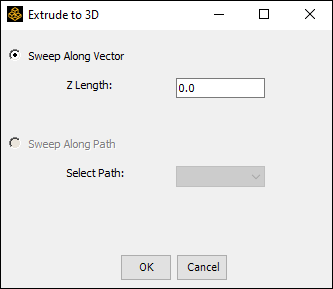
- Click Sweep Along Vector to extrude along the z axis. Z length is the input parameter.
- Click Sweep Along Path to extrude along
a selected path.
Note:
3D models of cables are hard to solve if the ratio of extruded length to cross-section diameter is high.
The Cable Modeling - Automotive dialog box appears with the Cable Parameters listed.
The wire radii are adjusted downward very slightly (on the order of 0.1%) at the end of the packing process to eliminate any residual overlaps between the wires and to make the model easier to mesh.
The Circle Packing algorithm is used to compute the values. It tries to automatically pack the conductors in the bundle tightly with a minimum of empty space between them. It generates and tests a large number of random variations in the conductor positions and attempts to minimize the overall diameter of the bundle.