
Assign Wave Ports for Modal Solutions
This section outlines the steps for defining excitations for modal solutions.
- Select coplanar face(s) that you want to excite.
- Click HFSS>Excitations>Assign>Wave
Port
The Wave Port dialog menu appears with the General tab selected.
- Enter the name of the wave port.
- Specify the number of modes for a port.
- If necessary define the integration lines
for each mode, and set the characteristic impedance. and specify whether
to filter modes for the reporter.
Note:
For more information about the Integration Lines, see Defining an integration line.
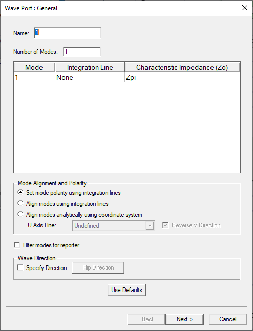
- You can specify whether to filter modes for the reporter. See Define Mode Alignment and Polarity.
-
A checkbox for Wave Direction allows you to specify the direction indicated by an arrow in the modeler window. You can flip the direction by clicking an enabled Flip Direction button.
If you specify direction, a PEC cap is not required for an internal wave port.

In the “Properties” page, the “Wave Direction” specifies the normal direction to a port surface as the wave propagation direction.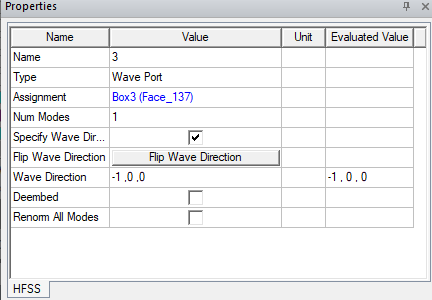
Similar to shell elements, the solver would treat the port surface as a split two side sheet, with the “Wave Direction” side as wave port and the other side as PEC. Put in way, this approach shrinks the sides of an otherwise PEC backing object to zero thinness, but leaves the top and bottom surfaces intact.
Automatic PEC Creation on Modal Wave Ports
In HFSS, A wave port must have 'solve inside' objects on one side only. An internal wave port can include a PEC object to be attached to and cover the opposite side.
This HFSS Boundary Assignment Option automatically adds a PEC backing to every newly created wave port when necessary. When a new wave port is created and requires a PEC backing, a dialog window opens to let users create such backing by extruding the port face with specified thickness. You have the option to flip the side of the PEC backing. You can also set the thickness as a variable.
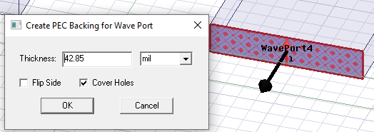
After clicking OK, the PEC backing is created and the new PEC object appears in the History tree.
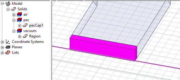
Once the PEC cap is created it is associated with the port. If you edit the geometry of the port or the geometry/material of the cap, association is deleted and a message is issued. If you reassign or delete the port, the PEC cap is deleted, and a warning is issued.
For an example, see Automatic PEC Creation for Wave Ports.