


Profiling allows you to customize medini analyze projects to your needs by extending the data model by new properties (fields). A profile property enhances all objects in the scope of a project consistently with new features. In the simplest way such a property can be the addition of a text field, but properties could also be references to other objects and even more sophisticated queries to show/aggregate data by navigation through the entire models are possible.
Profile properties appear in the UI like any normal attribute in the property view (separate tab), as columns if an element is shown in a table, or on forms ("Extended" section). Profile properties are accessible via validation constraints, scripting, or during reporting and hence provide a "first-class" extension mechanism.[14]
Currently, profiling is supported at almost any object type (i.e. meta class) with the following exceptions:
MATLAB/Simulink elements (deprecated)
Failure Collections
You can add a new property in one of the following ways:
In the Project Settings dialog, select Profiling
In the Table Editor, in the context menu of a header, select Add Column(see General aspects for table editors)
In most form editors, click the Customize link to open the settings dialog (see General aspects for form editors)
In the import preview page of the CSV/Excel import wizard, add a new mapping target column (see Using the CSV/Excel import wizard)
The Add Column action asks for the name of the property and simply adds it to the table. Using this action always creates properties of type text. If other types are required, create them using the Project Settings.
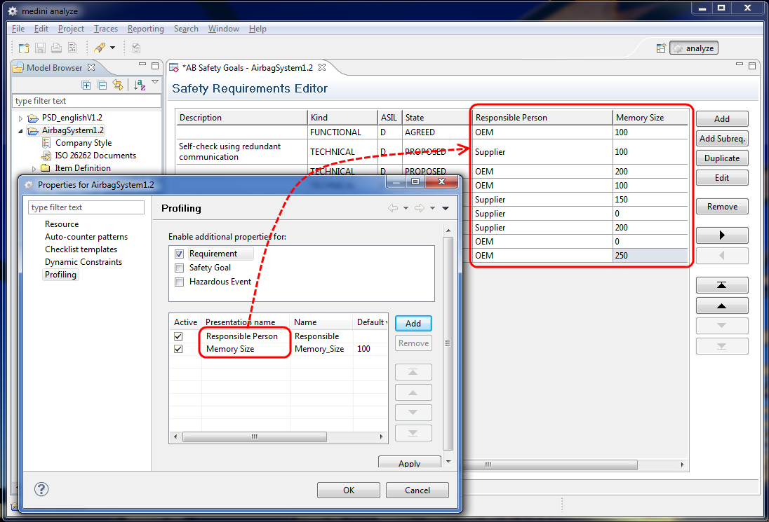
The profile section in the Project Settings dialog looks as follows.
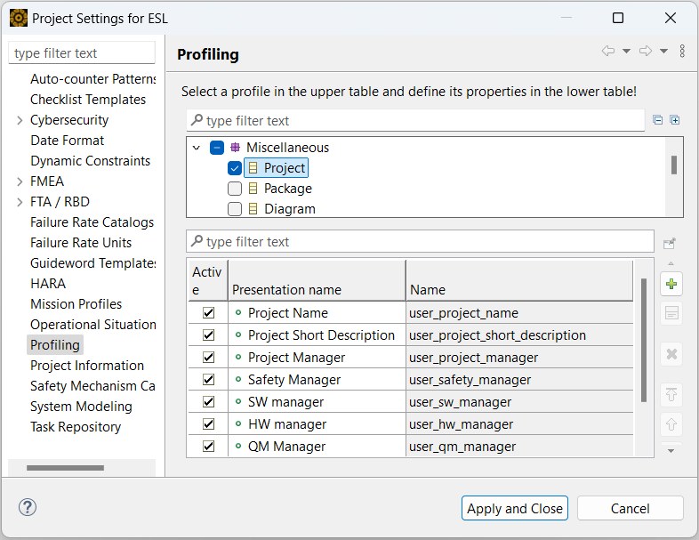
In the upper part of the dialog you can select which elements should be profiled. Select the check box to activate the profile settings for the current project. Clear the check box to disable the profile again.
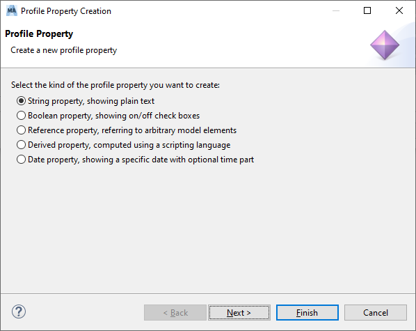
In the lower part of the dialog, you can specify the properties to add to the selected element. Click the [+] button to create a new entry in the table. Specify the details of the new property in a wizard dialog. On the first page of the dialog, choose the type of property to be created. Ansys medini analyze supports:
String property for text properties
Boolean property for on/off or true/false type of properties
Reference property, with which you can refer to other model elements from this property
Derived property, whose values are computed by a script at the time the property is accessed while using the tool
Date property, which provides a date picker and an optional time picker
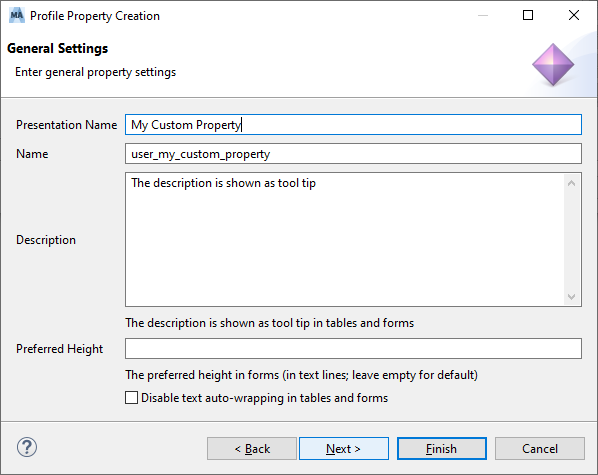
On the next wizard page, provide a Presentation Name for the new property. Choose any descriptive string. The presentation name is displayed in the table editor as the column title for the profile element.
An internal Name based on the provided presentation name is automatically created.
Note that the internal name for each property must be unique in the context of the element. Moreover, the lexical rules for identifiers in programming languages apply: the name must consist of at least one letter which may be followed by a sequence of letters and digits. Spaces as well as any special characters are not allowed. This name will be used for the internal management of profile data and is the identifier under which it is accessed in validation rules, scripting, and reporting.
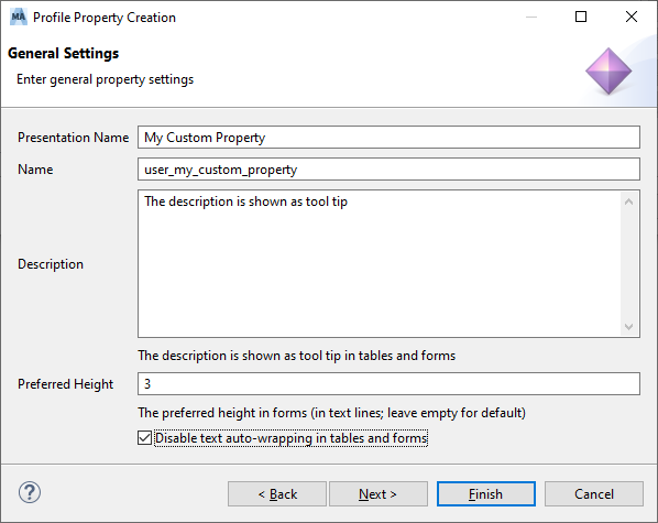
You can use the Preferred Height attribute to specify the height of the input field in form editors only. It does not work in tables or other kind of editors. The height is specified in number of lines. If the field is left empty, the default height is used.
Select the Disable text auto-wrapping in tables and forms check box to specify that the tool should automatically wrap text if it does not fit into the input field or cell in form or table editors.
The following wizard pages and the usage of the profile property depend on the type which has been selected for the property on the first page. These are described in more detail below.
When you are done, click the Finish button in the wizard dialog to create the new property.
Select or clear the check boxes in front of each property to activate or deactivate properties for an active profile.
Use the buttons on the right to add a new property, remove an already-defined property, or change the order of the properties.
Click Apply and Close to close the project settings dialog the profile properties and apply the update to the project.
If the element is to be displayed as a column in a table (such as Safety Goal or Hazardous Event), then use the table header context menu: Right-click in the header and select the user-defined properties you want. The corresponding column(s) are displayed in the table view. An example is shown in the next figure.
For other elements, a new field is added to the presentation form, such as for an FMEA Worksheet.
You can assign values to the properties of all elements using the Properties view. Click an element in the diagram editor (such as FTA or the Goal editor) or in the Model Browser. The Properties view shows the profile properties of the element. Note that if there is more than one tab in the Properties view, you have to select the Profile tab first.

The properties view is also available for table or worksheet cells that show exactly one element. You can usually recognize element cells by the presence of a label icon. For other table cells, such as text cells, the element from which the cell text or content comes from is chosen for the properties view.
To open the Properties view, select an element in the Model Browser and choose Show Properties View.
You can freely modify or delete profile properties. Just click the property you want to modify to change the presentation name as well as the default value. Changes to the default value apply only to new table entries created after the modification of the profile property.
Note: When you deactivate a profile or a single property, the element is only hidden from display on the corresponding editor. The properties of a profile as well as the values of the properties themselves are kept in the project. When you activate the profile or the property again, the previously-defined properties and property values reappear. If, however, you remove a property completely from a profile, all data values related to that property are also removed. In this case a warning is shown.
It is possible to specify a default value for the property in form of a string as well as a set of predefined values for the property in form of an enumeration type.
The values are entered in the predefined values section. It is possible to add and remove predefined values as well as to change their order (this will influence the controls in the corresponding editors when the values are used).
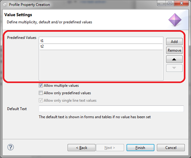
The following options can be specified by using corresponding check boxes:
"Allow multiple values" - if enabled, multiple values of the predefined value list can be selected in the fields or cells of the form or table editors which display the property.
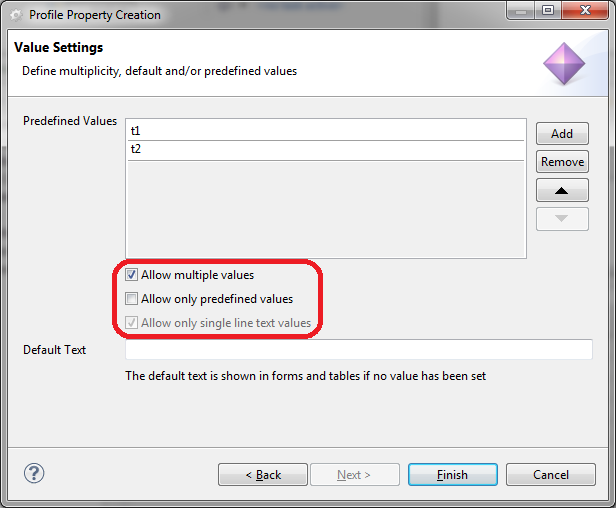
"Allow only predefined values" - if specified, only the specified predefined values can be selected in the form or table editors when the property is used. Otherwise, it is possible to enter text which is not part of the predefined values.
"Allow only single line text values" - if specified, no line breaks can be entered in the fields or cells of the corresponding table and form editor which show the property. (This is automatically enabled when predefined values are specified.)
The following pictures show the definition and the corresponding usage of a property with and without the multiple value option.
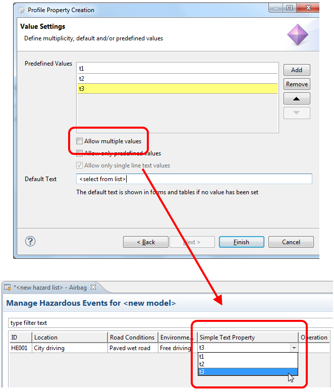
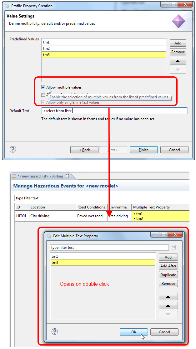
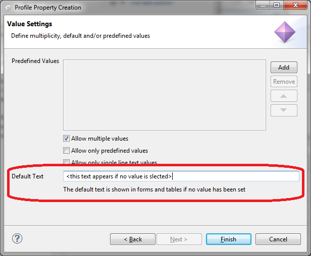
In the field "Default Text" it is possible to specify a text which is shown for the property after the element is created. This text can either be one of the predefined values or an arbitrary string. Please note with the multiple value option disabled the definition of such default values is only effective for elements that are created after the default value is specified. For existing elements, it is not applied. With the multiple value option enabled the default text is shown for all elements for which no value is selected.
The reference type property enables you to create links to model elements within a project or in other local or shared projects. When you create a new reference type property, you select a model element type so you can refer to its elements using the property. After you have created the reference type property, use it to, for example, include the referenced elements in a table.
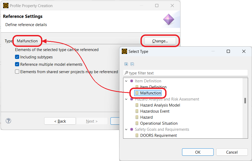
To select the model element type, in the Reference Settings dialog, click the Change... button to open the selection dialog, as shown in the graphic below. The dialog lists all model element types.
Model element types are defined in a hierarchy in the metamodel, for example, the type DC Worksheet is a specialization of FMEA Worksheet. To reference model elements of all types, select the type Any.To include subtypes, in the Reference Settings dialog, select the Including Subtypes check box. For more information about the medini analyze metamodel, see the Metamodel Guide (login required).
To be able to add more than one referred model element to the reference property, select the Reference multiple model elements check box.
To also be able to include elements from models in shared server projects, select the Elements from shared server projects may be referenced check box. Note that you can also add elements from versions of shared server projects.
After you have added your new reference property to your project, complete these steps to add references to elements.
In your project, open the Properties view and click the Profile tab.
Your new reference type property is now displayed as a row in the property table.
To add element references using drag and drop, pin the Properties view, then drag elements from the Model Browser to the property.
If you did not select Reference multiple model elements, the next element you drag replaces the previous element.
If you selected Reference multiple model elements, you can add more than one element. To replace existing elements with a single element, press the Shift key during drag and drop.
To add or modify the element references selection, double-click an element reference to open the Select referenced Object(s) dialog. Note that any shared projects are also listed, even if they are not loaded.
If you selected Reference multiple model elements, you can add more than one element. If not, you can only select a single element.
Note that elements dragged from shared projects (or versions of shared projects) have a special icon, with an arrow in the lower-right corner indicating that this is a reference to an element.
After you add elements, you have these options:
To see the project path to the original element(s), hover over the reference(s) until you see the "Referenced Elements" tool tip.
To select the original element(s) in the Model Browser, right-click the reference(s) and select Show Element(s) in Browser.
Note that if any of the original element(s) are located in shared project(s), and the project(s) are not loaded, medini analyze offers to load the project(s) for you.
To remove all references, right-click the reference(s) and select Clear.
If you rename or move a referenced element in a shared project, you can update the reference information in the referencing project. Right-click the reference(s) and select Update Cross-Project Link Info.
If a referenced element is deleted from a shared project, the reference is not automatically removed from the profile property values. Double-click to open the Select referenced Object(s) dialog and remove the reference there.
After you have created a reference type property, you can display it as a column in an appropriate table, depending on how you defined the property. Simply right-click in the table header to list the available columns and select your reference property from the list.
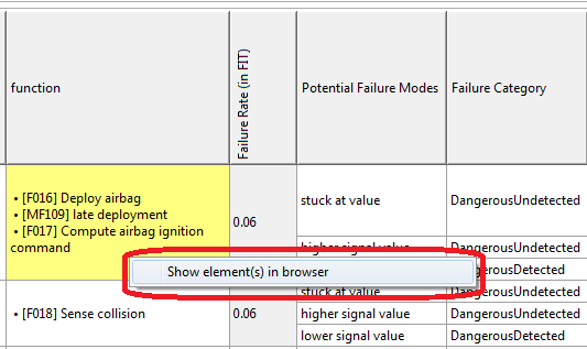
The following graphic shows an example of using a reference type property in a table view. To select additional elements, or to clear elements, double-click the cell in the table editor to open the Select referenced Object(s) dialog.
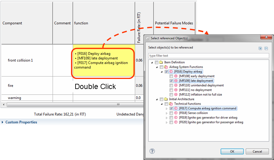
To locate the referred elements in the Model Browser, right-click in the cell and select Show element(s) in browser.
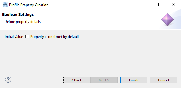
Properties of the type "Boolean" can be used to express on/off resp. true/false states. A check box control is used in forms and tables to represent and edit such a property. An initial value can be defined, by default new properties are initialized with "false" resp. "off". False/off values are represented by an unchecked box, true/on by a checked checkbox instead.
Properties of the type "Date" can be used to add information about dates and time to elements. A date/time picker dialog supports you in setting the desired value.
Properties of the type "derived" are used to display content that is computed at runtime out of the actual models. In the Wizard for the creation of the property, a script has to be specified, that is used to calculate the content to be displayed when the property is visualized in an editor. The language currently supported is OCL. The script has to be provided as text in the dialog field.
A default value can be specified as well. The default value is used, when the script evaluates to null, to the empty list or to invalid.
Since it is possible to formulate scripts that contain loops, the evaluation of the script is stopped after a certain period in time. It is also possible to stop the execution of the thread that evaluates the script. Note, that the evaluation is always executed in an own thread and does not block the other operations of medini analyze.
As long as the script is evaluated, the editor shows the string "evaluating".
In the currently supported OCL language for the script specification, the variable "self" denotes the actual model element of the type for which the profile property is defined.
An example script is to be seen in the following figure.
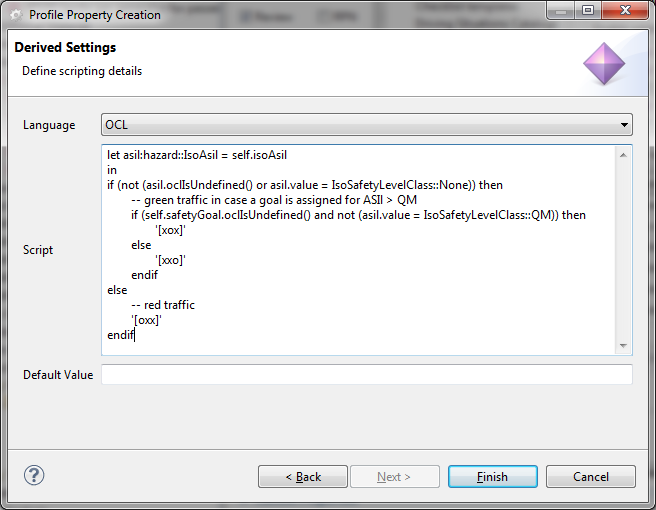
In the example, the property "Safety Goal Assignment" is created for elements of type "Hazardous Event". The variable "self " refers to an actual Hazardous Event in the model. The script evaluates the presence of a safety goal for an hazardous event and displays the evaluation result as a simple traffic light. It creates the following output in a hazard table:
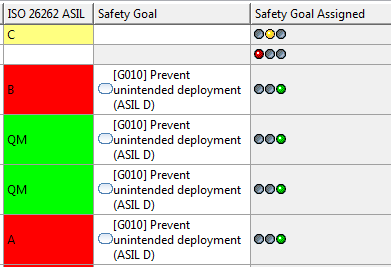
Note that there is further support for other icons and coloring of cells and even a combination of them, for example:
Please refer to the Ansys medini analyze Scripting Guide for more information.
[14] The term profiling is used in the sense of a profile known from modeling languages such as UML: it is a well-defined extension of the data model of the tool.