


This chapter provides a quick walk-through for medini analyze for automotive functional safety according to ISO 26262.
Please note, this chapter does not cover all aspects and details of medini analyze. Always check also the other chapters of the user manual for more information.
Let's assume we are requested to provide a safety analysis for an airbag system including only front airbags (yes, we know, modern cars have multiple airbags, but here we just want to keep it simple). Our system shall consist of a front sensor, the main airbag controller and the airbags themselves. We should provide a hazard and risk analysis, derive the safety goals and safety requirements as well as perform the detailed safety analysis for the anticipated design of the system.
If you start medini analyze for the first time, you will see the main application with the Model Browser at the left side and the main work area in the center. In order to begin with our tasks we need to create first a medini analyze project.
Do that by selecting "File > New analyze project" and providing a name for the project. Please note, a name must consist of characters, digits or the symbols ".", "-", or "_". Other symbols including spaces are not allowed. Make sure you select the "Automotive (ISO 26262)" profile so that the ISO 26262 domain profile is activated.
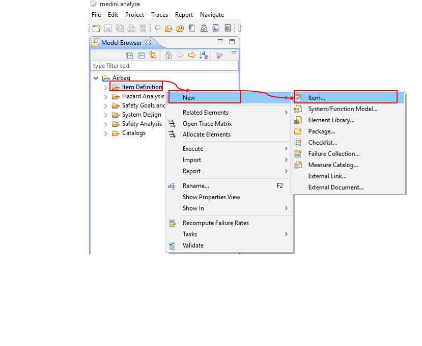
Click on "Finish" and the new project will appear in the Model Browser. If you now expand the project contents, you will see 5 basic packages, each for a specific activity of the safety life-cycle. Let's start with a high level description of our system. The system or function under safety analysis is called Item. To create an item, chose the option "New->Item" from the context menu of the "Item Definition" package. Again you have to give it a name (which can be the same as the project name).
Now, the newly created item appears in the "Item Definition" package and the specification page for the item appears in the main working window. You should give a meaningful and concise description of the item in the "Description" field. You may add properties to the item by using the "Customize" link.
Moreover, you may also add additional explanatory material such as sketches or figures or other documents as external documents to the "Item Definition" package. Such external documents are managed and versioned together with the medini analyze project. To add such an external document, select "New-> External Document" from the context menu of the "Item Definition" package in the Model Browser.
Please note that you can add external documents to any of the packages in medini analyze.
As a next step you may want to specify that there is a relation between the item definition and the external document. To do that, select the item entry and then the external document while pressing the "Ctrl"-key. Both entries will be marked as selected. Complete the action by selecting "Link with trace" from the context menu of any of the two selected elements.
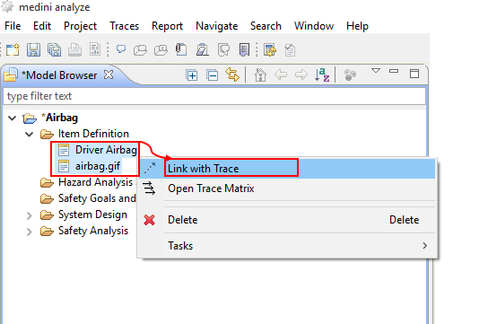
You can create traces between any kind of elements as described above, by selecting the two elements in the Model Browser and choosing "Link with Trace" from the context menu.
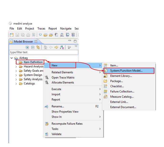
To further refine the item definition, you may specify a set of functions for the item. The context menu of the Item Definition package in the Model Browser will be used for that purpose ("New->System/Function Model...").

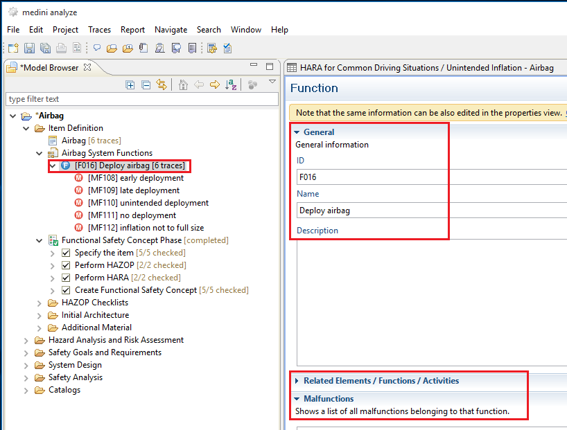
This model again can be structured into sub-packages and finally functions using the appropriate context menu entry. In the model tree view, the new model will appear in the item package it belongs to. Double-clicking a function opens a detailed specification page.
Note, functions can be created or visualized also using the graphical editor.
Note, relations between functions may be added/modified/deleted using the detailed function specification editor or by putting the function(s) on a diagram and connect them by the appropriate relations.
It is recommended to specify also the rough or preliminary architecture of the item in the item definition package. This architecture should contain a high level view on those components, sensors, actuators and their connections that implement the desired functions. Each of these elements will be traceable.
To do that, you select "New-> System/Function Model..." from the context menu of "Item Definition" and give a name to the architecture model in the dialog.
A system/function model editor with an empty diagram will open immediately. Furthermore, a new model element appears in the item definition package. If you click the small triangle left to the new model element, you will find another model element, which is the diagram to work with.
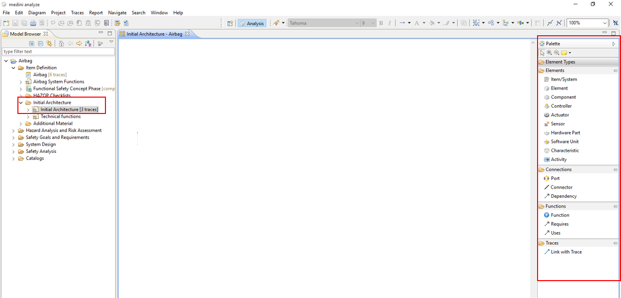
You can use the palette on the right in order to specify systems, components, elements, actuators, controllers, sensors, hardware parts and software units as well as their communication ports and connectors which will be part of the items preliminary architecture. Furthermore, behavior can be specified by functions and activities. (It is also possible to specify special characteristics, but this is not necessary for the time being as it is relevant only in context of special safety analysis methods.) Entries from the Palette can be selected and moved with the mouse to the diagram to create an element there. You can use fill colors, line colors and different fonts from the menu on top of medini analyze in order to make the diagrams more coherent for a user.
Note, architecture models may be hierarchically structured, i.e. elements may contain other elements. Just drag and drop elements inside them.
To ease the work with large diagram, the drawing area may be maximized in size. Double click on the diagram tab and the diagram will use the full size of medini analyze. Double clicking there again returns to the previous tool layout.
Note, this maximization is available for all views of medini analyze.
All the elements you modeled in the diagram appear also in the Model Browser (with subtree-structures for hierarchies).
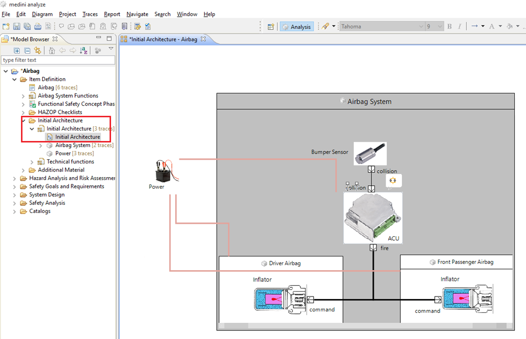
Our item architecture contains the front sensor (of type Sensor), the driver & front passenger airbags and their initiators (of type Element and Actuator respectively) and the ACU (of type Controller).
In the next step, we will perform the hazard and risk analysis for the item. The basic procedure here is to identify the potential malfunctions of the system, and to put them into the context of operational situations. For each of such combination (called hazardous event) we execute a risk analysis, i.e. we identify the severity of the hazard, the probability of the exposure to it and its controllability.
We recommend performing a hazard and risk analysis for each function the system provides. First, let's have a look on the airbag's function to deploy. A potential failure (or malfunction) is that the airbag deploys unintended. Of course it depends on the operational situation whether or not this is harmful for the driver or passengers.
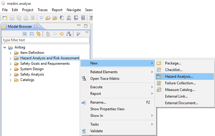
To create a hazard analysis and risk assessment worksheet, select "New->Hazard Analysis..." from the context menu of the "Hazard Analysis and Risk Assessment" package, give it a name, select the "Frontairbag" as related item and click on Finish.
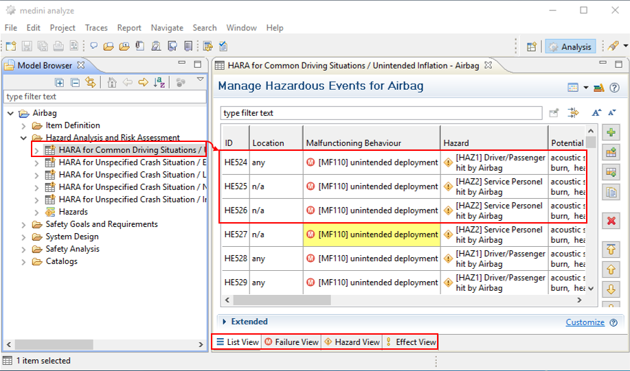
The new worksheet is opened immediately. Now you have to specify an operational situation and item usage, select the malfunction of the item and finally describe the potential hazard in this context.
The tabs in the lower part of the editor enable you to focus on the failures, hazards or effects. In these views the entries in the table are grouped and the columns change their position.
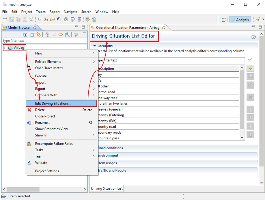
For some of the properties of a operational situation, you may either select a predefined value or just type in a description if the predefined values don't fit to what you want to express.
Note, you may also extend or modify the list of existing operational situation parameters. Just use the context menu of the whole project as shown in the following picture. A window will open that allows editing all operational situation parameters.
The final step of the hazard and Risk analysis is the determination of the safety integrity levels. Click into the cell in the "ASIL" column of the worksheet. A wizard will open that guides you step-by-step through the risk analysis for this hazardous event. Select the appropriate values for the parameters and give a justification for each selection. In the case of an unintended deployment of the driver airbag during fast driving on a highway, the driver may loose control over the car and crash. Thus the severity for the driver and the passengers is fatal and we choose "S3", the exposure probability is high as the car is built to be operated on highways, and the controllability is very low: the driver may not be able to see anything after the airbag deploys or may even be injured by it.
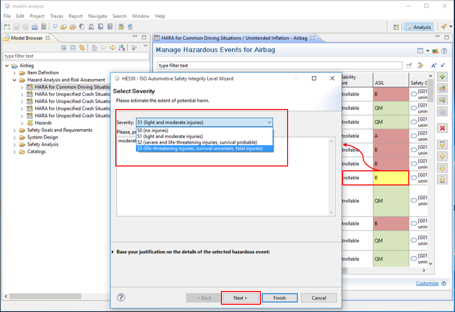
After specifying values for all three parameters, the resulting ASIL will be displayed (ASIL B in our case).

For each hazardous event with an ASIL higher than QM, we have to assign a safety goal, either by defining a new one or by using an existing one. If you click "Next" on the ASIL wizard, the dialog to define or re-use safety goals appears. Safety goals are managed together with safety requirements as safety requirements models in the "Safety Goals and Requirements" package of the project. In the dialog you either can create and name a new safety goal or select an existing one. After providing a name and a short description for the safety goal complete this activity by selecting the safety requirement model to which the newly created goal should be added.
Note, a safety goal should be the "inverse" of the hazardous event.

After finishing this step, a new safety requirement model "AB Safety Goals" appears in the Model Browser in the "Safety Goals and Requirements" package. This model contains the newly created safety goal "prevent an unintended airbag deployment". If you double-click the diagram icon, the (empty) goal and requirements diagram opens. The safety goals from the Model Browser can be put onto the diagram using drag & drop.

The safety goal will automatically obtain an identifier. You may use the formatting mechanisms like coloring, font size etc. similar as in the system/function model editor. The palette right to the diagram contains the elements that you can use on this diagram, we will focus on a few here only; a more detailed description is given in "Safety Goals and Safety Requirements" in the Ansys medini analyze User Guide.
Safety requirements define the necessary measures to fulfill a safety goal. Safety requirements must have at least the same ASIL as the corresponding safety goal. Let's define a functional safety requirement "prevent the ACU to send a deployment command when the car is not involved in an accident" by selecting "Requirement" from the palette and dragging it to the diagram. An identifier as well as a default value for the ASIL (D) will automatically be assigned to the new requirement. You just have to add the requirements name.
In order to specify that the requirement contributes to the safety goal, we select "Contribution" from the palette, and connect the requirement and the safety goal (keep the left mouse key pressed). In order to modify the properties of a requirement (e.g. name, ASIL etc) also the corresponding requirements editor can be used (see "Safety Goals and Safety Requirements" in the Ansys medini analyze User Guide for details).
To identify the set of safety requirements which are necessary to fulfill a safety goal, we can use the fault-tree-modeling technique. To create a new fault tree model, open the "Safety Analysis" package and select "New->FTA Model" from the context menu of the "FTA Models" package. (Alternatively, press "Create FTA" from the context menu of the safety goal under analysis.)
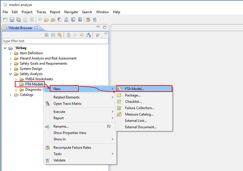
Provide the name for the FTA. It usually specifies a violation of the safety goal. As result, the FTA model, its diagram and the top-level event are created. The relation between the safety goal and the FTA can be established again by a trace: Select the safety goal and the FTA model in the Model Browser (keeping "Ctrl"-key pressed) and perform "Link with Trace" from the context menu.
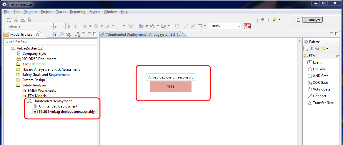
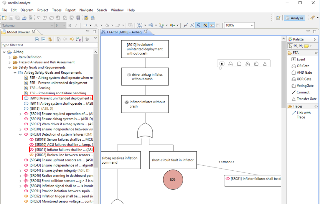
As usual the diagram is opened directly after creating the model. The top-level event is already shown on the diagram and you can start the analysis work. This involves the creation of further events, gates and connections by drag & drop of appropriate elements from the drawing palette.
In our very simplified example, we identify that an unintended deployment of the airbag will happen if the ACU sends a deployment command to the airbag in an uncritical situation. This in turn can happen if either the front collision sensor wrongly senses a collision or if the communication channel between the sensor and the ACU does not work properly.
We specify this situation by adding these three events to the diagram and use appropriate logical gates and connections to build the fault tree. Each event will get an automatically assigned identifier.
Don't forget to add traces between the events of the FTA and the related elements of the item architecture using the "quick trace" feature and to provide the name for the event. In order to short-cut, you may drag&drop elements from the System/Function Model to the fault tree diagram. This will create an FTA event which is connected by a trace automatically.
Note, connections into the direction of the leaf-nodes will be automatically created when dropping an element from the palette (event or gate) onto an existing element in the diagram (event, gate).
Some convenient features support the handling and understanding of even large fault trees. If you double-click an event or gate on the diagram, the subtree starting at that element will be folded in, double-clicking again restores the subtree. The "Arrange Subtree" function in an elements context menu arranges the tree to some nice layout.
After identifying the events that result in an unintended deployment of the airbag, we can derive now new (or better more detailed) functional safety requirements in order to prevent these events to happen:
we have to provide a certain degree of redundancy for sensing a collision
we should deploy redundancy also for the communication
we should deploy "watch dogs" to monitor the system and turn off the airbag system in case of anomalies.
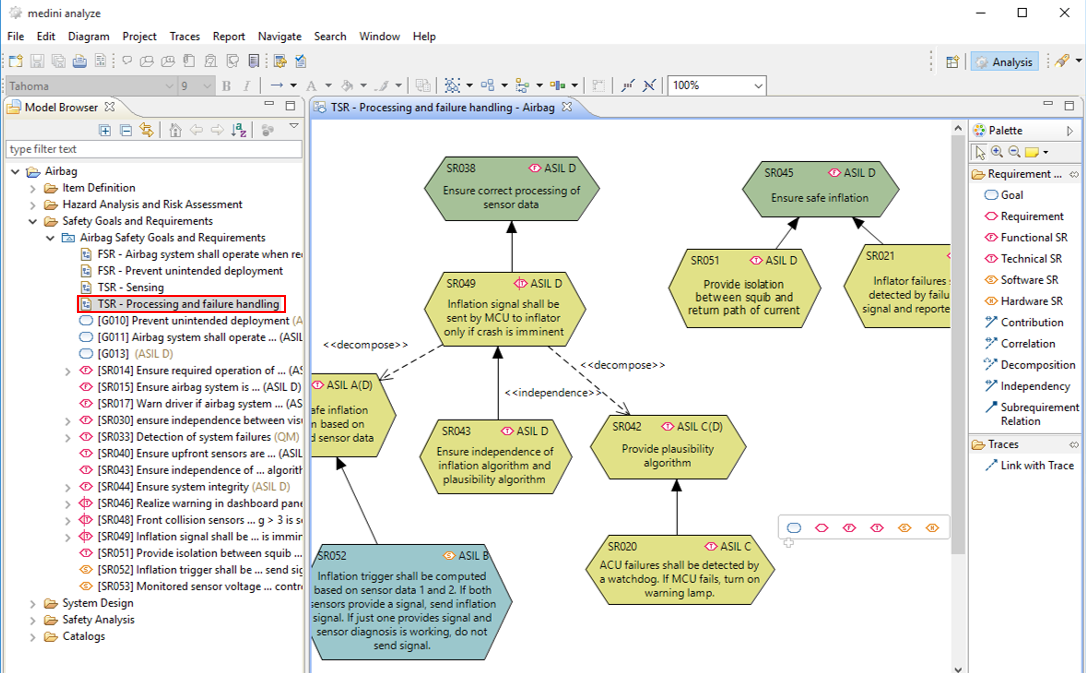
Let's go back to the safety goal and requirements diagram and add these three functional requirements (including appropriate contribution and sub-requirement relationships). As these requirements are a refinement of our existing requirement, they shall be modelled as sub-requirements. Just drop a requirement from the palette on an existing requirement at the diagram and the sub-requirements relation will be created automatically.
Moreover, we create traces between the new requirements and the events in the FTA as a justification for the new requirements.
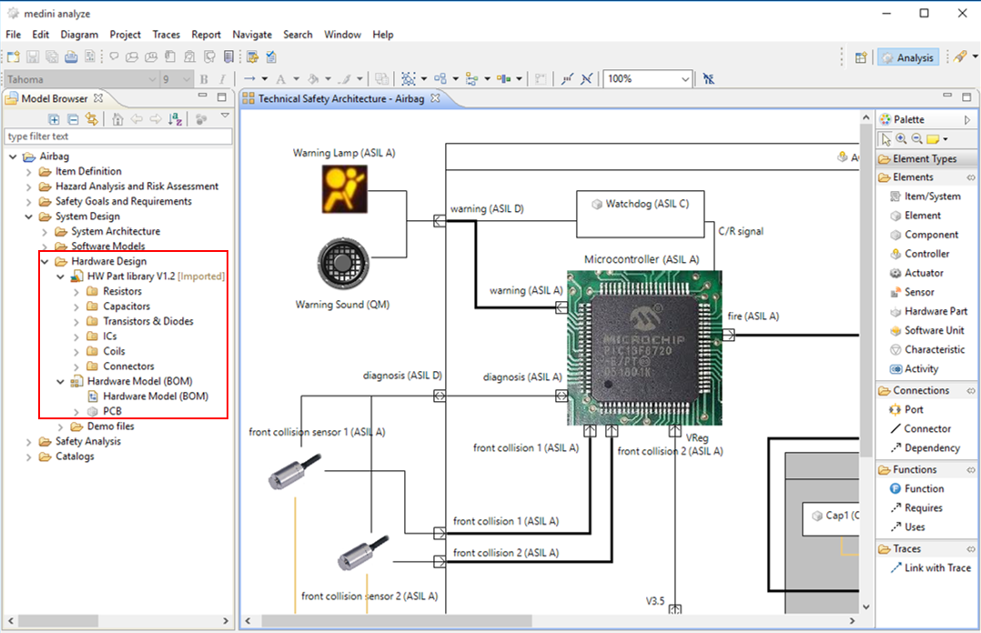
After completing the requirements definition we will provide now a more detailed system architecture that reflects the safety requirements we identified. As this is already a part of the design, the detailed architecture will be stored in the "System Design" folder. Open the package "System Design" in the Model Browser, and select "New->System/Function Model..." from the context menu of the package "Hardware Models". After giving a name, the model is created in the "Hardware Models" package.
We start the design with drawing the ACU by selecting "Controller" from the palette and dropping it on the diagram. Subsequently, we specify the internal elements as parts of the ACU (e.g. sensors, MCU, interfaces etc.), using the "Element" element of the palette. The connecting points to the outside can be added as ports, select "Port" from the palette. This (still simplified) architecture of the ACU is shown in the next figure.
Now we have to express the allocation of the safety requirements onto elements of the system architecture by the means of traces. In order to do so, we again may use the quick trace feature. Select an element of the system architecture and a safety requirement and link them with a trace. However, a more convenient way is to use the trace matrix. The matrix is opened by selecting "Allocate Elements" from the context menu of the "Safety Goals and Requirements" package in the Model Browser and choosing our architecture model as target model.
The trace matrix will show all elements of the two packages as rows resp. columns. Clicking in a cell of the matrix will create a trace between the elements corresponding to row and column of the cell and indicate this by a tick-symbol. Inversely, clicking on a marked cell will remove this trace again.
Folding/unfolding of rows/columns by clicking the "+" and "-" symbols of nested structures as well as user definable filters assist the handling of even large trace matrices.

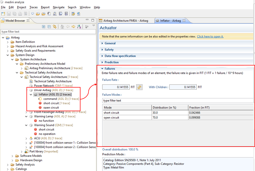
The architecture definition has to be accompanied by an analysis of potential (known) failure modes of the components of the system and of the effect of such failure modes. medini analyze includes the FMEA technique (Failure Mode and Effect Analysis) for this purpose. As a precondition for the FMEA we first specify the failure modes for the components of our architecture. This is done by opening the system element form editor "Open With > System Element Editor" from the context menu of the architecture elements in the Model Browser.

We have to use the "Failures" section of the form editor to enter the failure modes.
We can use the "+" button to enter new failure modes. The failure modes assigned to an element are shown in the Model Browser as sub-entries for the element. We can also add the failure rate of the component and the distribution of the failure rate among its different failure modes here. The distribution needs to be specified in percentage.
Now we start the FMEA by creating an initial component FMEA worksheet from the system architecture. Select "Derive FMEA Worksheet..." from the context menu of the system/function model in the Model Browser to do so.

The newly created FMEA worksheet will be stored in the "FMEA Worksheets" folder of the "Safety Analyses" package. This FMEA worksheet contains entries for all components of the system. In addition, the worksheet is initialized with all failure modes and resulting failure rates that have been specified for the systems' components.
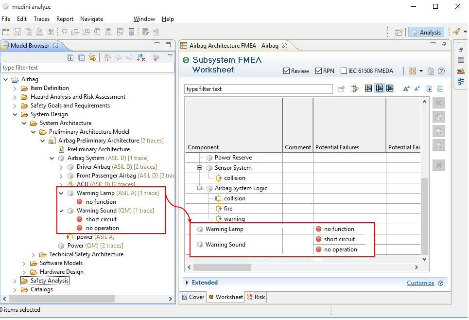
During an assessment of the architecture the values for all other fields of the FMEA worksheet have to be entered. Medini analyze automatically computes from these data the risk priority number (RPN). If necessary the architecture design has to be modified and subsequently reviewed again by FMEA.
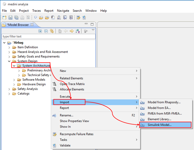
In the final step we complete our design by the software model. After designing this model with MATLAB/Simulink you can load your Simulink software models directly into medini analyze. This allows you to include them into your safety analysis and to create traces between the software model and the already existing elements of the safety analysis and design. In order to import a Simulink model, select "Import-> Simulink Model..." from the context menu of the "Software models" package in the "System Design" package.
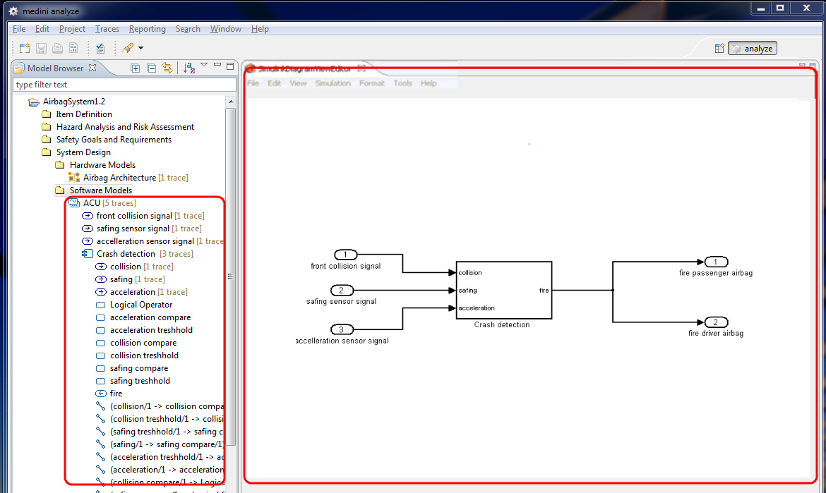
If you expand the model tree in the Model Browser, you can see now all elements of the Simulink model. If you double click on the model ("ACUControl" in our example), Simulink is executed to display the diagrams embedded in medini analyze.
Note, the import of Simulink models can be performed without having MATLAB/Simulink on the computer running medini analyze. However, in order to graphically display the Simulink model, a licensed installation of MATLAB/Simulink is required!
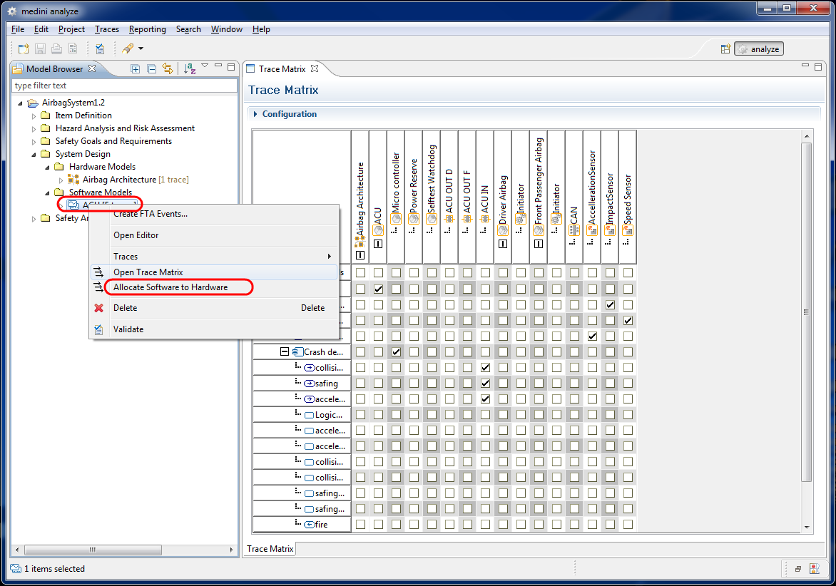
Now you can define the mapping of the software onto the hardware by specifying which Simulink port is connected to which port in architecture model. You also may specify which controller is running which Simulink subsystem. In order to do so, select the "Allocate Software to Hardware" command from the context menu of the "Simulink Models" folder to open the appropriate trace matrix. The resulting relations are shown in the following trace matrix.
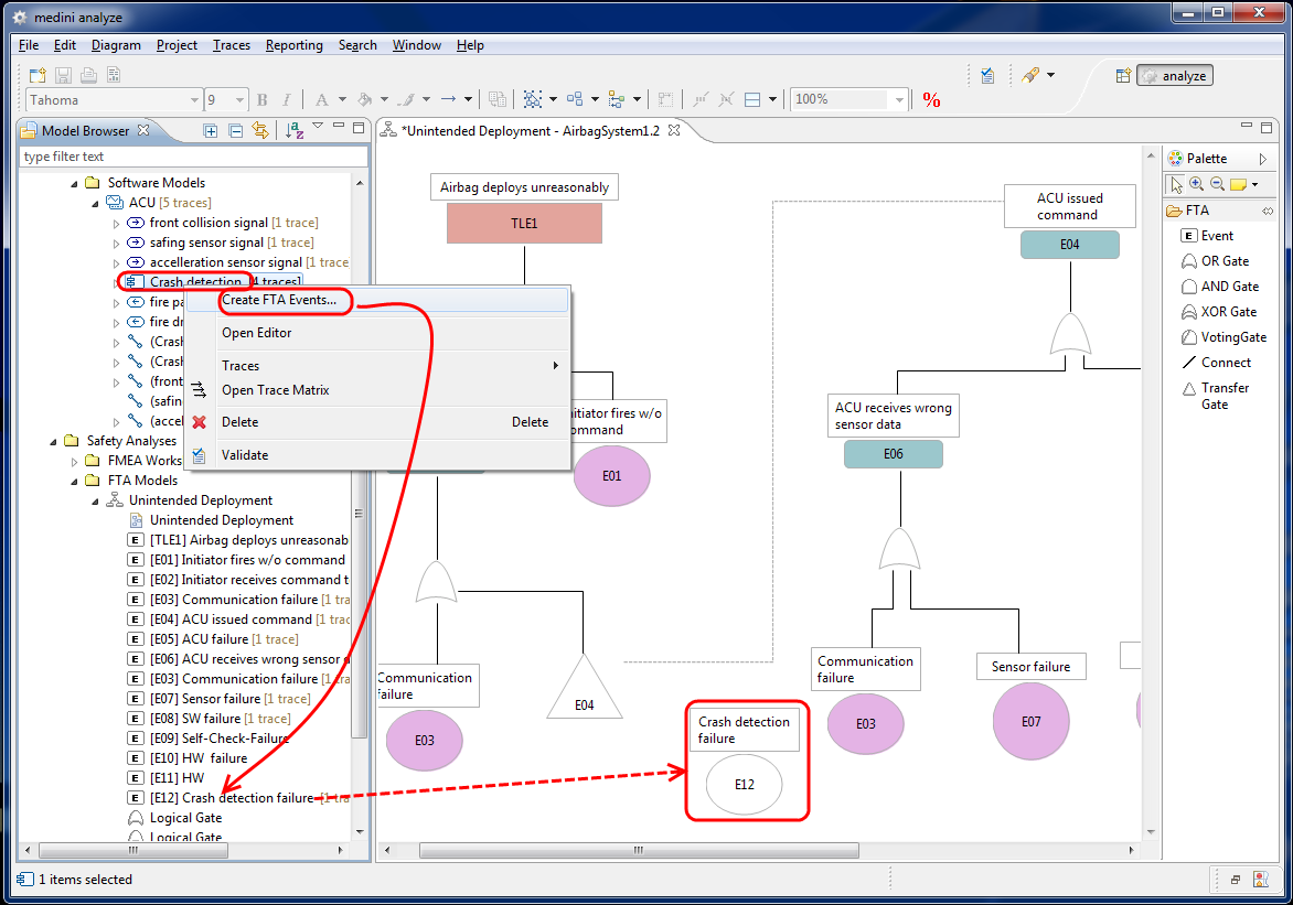
Apart from hardware-software traces you can of course also establish traces to other elements (e.g. between requirements and software model elements). Moreover, you can use the software model elements in your safety analysis, e.g. as source for events in the FTA. Just select "Create FTA Event(s) ..." in the context menu of the Simulink model element in the Model Browser and add the events to an existing FTA model or to a new FTA model.
As explained before the fault tree model has to be completed by gates and additional events before a detailed FTA can be performed.
This concludes the quick walk-through for medini analyze. You can now print your resulting diagrams using the "File -> Print" option from the diagram context menu (i.e. the context menu that appears when clicking the right mouse key in an empty area of the diagram. Moreover, medini analyze allows you to generate various kinds and formats of reports. You will find "Report" at the context menus of the following elements in the Model Browser and via the "Report" main menu entry:
Item definition
Hazard analysis and risk assessment models
Safety goals and requirements models
FMEA worksheets
FTA analysis worksheets
Checklists
Diagnostic Coverage (DC) worksheets
In the following sections, the features and various usage options of medini analyze are explained in detail.