


Solder Ball Creation allows you to define the solder ball parameters and mesh properties to create solder ball.
Solder Ball Creation Details view has the following options:
General
Control Type: Displays the control type for the selected operation.
Definition
Define by: Allows you to define the element size based on value or settings. The available options are:
Value: Defines the element size based on the provided value.
Settings: Defines the element size based on the settings under Mesh Settings in the Steps Details view.
Coordinate Define by: Allows you to define the coordinate points. The available options are:
Location: Allows you to use the coordinates from a picked location to define the coordinates to create the solder ball. You can select any location and click Apply in Coordinate to get the coordinates of the selected location. When Coordinate Define by is Location, the available option is:
Coordinate: Allows you to select the location coordinate based on coordinate systems.
Coordinate System: Allows you to specify the coordinate system to define the coordinates to create solder ball. When Coordinate Define by is Coordinate System, the available option is:
Coordinate System: Allows you to select the defined coordinate systems for creating solder balls. You can click
 to select from the
available list of coordinate systems that are defined under
the Coordinate Systems object in the
Tree outline.
to select from the
available list of coordinate systems that are defined under
the Coordinate Systems object in the
Tree outline.
Geometry Selection: Allows you to select the location coordinate based on your selection in the Geometry window.
X Coordinate: Allows you to set the X coordinate based on the selected Coordinate Define by option. The default value is 0.0 m. When Coordinate Define by is Coordinate System, X Coordinate displays the value of X coordinate. You can click
 on the right corner of the
option and click Publish to publish X
Coordinate to the Property Worksheet.
on the right corner of the
option and click Publish to publish X
Coordinate to the Property Worksheet.Y Coordinate: Allows you to set the Y coordinate based on the selected Coordinate Define by option. The default value is 0.0 mm. When Coordinate Define by is Coordinate System, Y Coordinate displays the value of Y coordinate. You can click
on the right corner of the option and click
Publish to publish Y Coordinate to
the Property Worksheet.Z Coordinate: Allows you to set the Z coordinate based on the selected Coordinate Define by option. The default value is 0.0 mm. When Coordinate Define by is Coordinate System, Z Coordinate displays the value of Z coordinate. You can click
on the right corner of the option and click
Publish to publish Z Coordinate to
the Property Worksheet.X Axis: Allows you to define the orientation along the X-axis. You can click on the right corner of the option and click Publish to publish X Axis to the Property Worksheet.
Y Axis: Allows you to define the orientation along the Y-axis. You can click on the right corner of the option and click Publish to publish Y Axis to the Property Worksheet.
Z Axis: Allows you to define the orientation along the Z-axis. You can click on the right corner of the option and click Publish to publish Z Axis to the Property Worksheet.
You can parameterize the X Coordinate, Y Coordinate, Z Coordinate, X Axis, Y Axis and Z Axis.
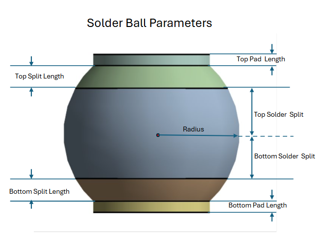
Solder Ball Parameters
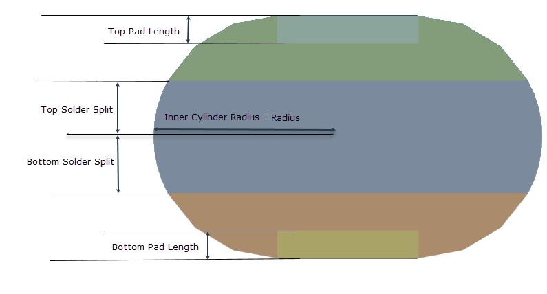
Solder Ball Shape: Allows you to specify the shape of the solder ball. The available options are Sphere and Torus. The default value is Sphere.
When the Solder Ball Shape is Sphere:
When the Solder Ball Shape is Torus:
Radius: Allows you to provide the radius of the solder ball. The default value is 0.5 mm. You can click
on the right corner of the
option and click Publish to publish
Radius to the Property Worksheet.
You can parameterize the Radius.Inner Cylinder Radius: Allows you to set the radius of the inner cylinder. Inner Cylinder Radius is available only when Solder Ball Shape is Torus. The default value is 0.55 mm. You can click
on the right corner of the option and click Publish to
publish Inner Cylinder Radius to the Property
Worksheet. You can parameterize the Inner Cylinder
Radius.Top Solder Split: Allows you to specify the distance from the center of the solder ball to the beginning of the top split. The default value is 0.25 mm. You can click
on the right corner of the option and click
Publish to publish Top Solder
Split to the Property Worksheet. You can
parameterize the Top Solder Split.Bottom Solder Split: Allows you to specify the distance from the center of the solder ball to the beginning of the bottom split. The default value is 0.25 mm. You can click
on the right corner of the
option and click Publish to publish Bottom
Solder Split to the Property Worksheet. You
can parameterize the Bottom Solder Split.Top Split Length: Allows you to specify the length of the top split from the origin of top split. Top Split Length is available only when Solder Ball Shape is Sphere. The default value is 0.125 mm. You can click
on the right corner of the option and click
Publish to publish Top Split
Length to the Property Worksheet. You can
parameterize the Top Split Length.Bottom Split Length: Allows you to specify the length of the bottom split from the origin of the bottom split. Bottom Split Length is available only when Solder Ball Shape is Sphere. The default value is 0.125 mm. You can click
on the right corner of the option and click
Publish to publish Bottom Split
Length to the Property Worksheet. You can
parameterize the Bottom Split Length.Top Pad Length: Allows you to specify the length of the solder ball top pad. For Sphere, a positive value creates an external pad above the top split, and a negative value creates an internal pad below the top split. For Torus, the absolute value is used and always creates an internal pad. The default value is 0.0625 mm. You can click
on the right corner of the option and click
Publish to publish Top Pad Length
to the Property Worksheet. You can parameterize the
Top Pad Length.Bottom Pad Length: Allows you to specify the length of the solder ball bottom pad. For Sphere, a positive value creates an external pad below the bottom split, and a negative value creates an internal pad above the bottom split. For Torus, the absolute value is used and always creates an internal pad. The default value is 0.0625 mm. You can click
on the right corner of
the option and click Publish to publish
Bottom Pad Length to the Property
Worksheet. You can parameterize the Bottom Pad
Length.
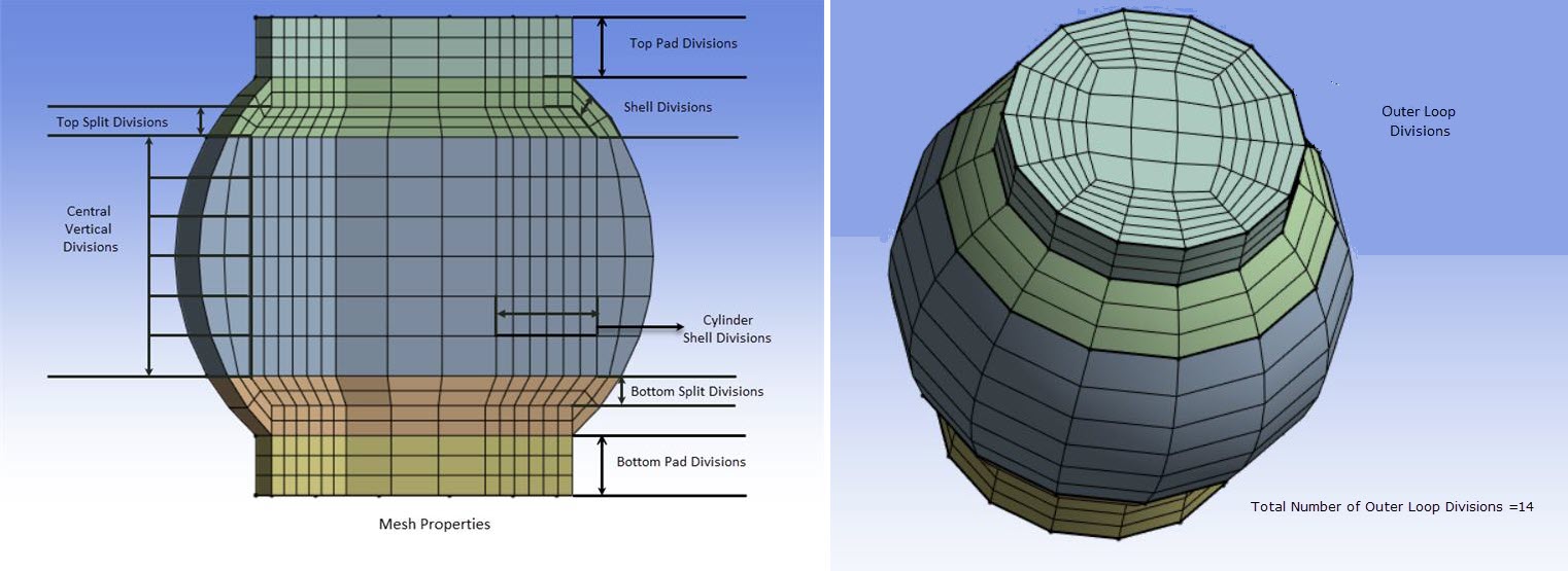
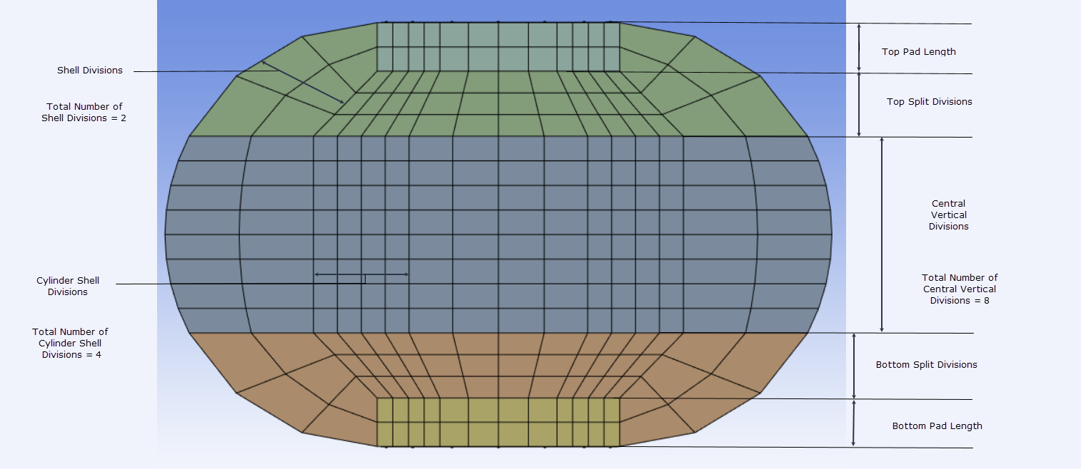
Mesh Properties
Outer Loop Divisions: Allows you to specify the number of outer loop divisions for the solder ball mesh. You cannot enter an odd values in Outer Loop Divisions. The default value is 14. You can click
on the right corner of the option and click
Publish to publish Outer Loop
Divisions to the Property Worksheet. You can
parameterize the Outer Loop Divisions.Shell Divisions: Allows you to specify the number of divisions for the outer shell of the solder ball mesh. The default value is 2. You can click
on the right corner of the option and click
Publish to publish Shell Divisions
to the Property Worksheet. You can parameterize the
Shell Divisions. Note: For Sphere, if the top pad and bottom pad lengths are negative, Shell Divisions controls the number of divisions in the top and bottom pad. For Torus, controls the number of divisions in the top and bottom pads and are always created as internal pads.
Cylinder Shell Divisions: Allows you to specify the number of divisions for the inner cylinder shell of the solder ball mesh. The default value is 3. You can click
on the right corner of the option and click
Publish to publish Cylinder Shell
Divisions to the Property Worksheet. You can
parameterize the Cylinder Shell Divisions.Central Vertical Divisions: Allows you to specify the number of vertical divisions for the center of the solder ball mesh, excluding top and bottom splits. The default value for is 5. You can click
on the right corner of the option and click
Publish to publish Central Vertical
Divisions to the Property Worksheet. You can
parameterize the Central Vertical Divisions.Top Split Divisions: Allows you to specify the number of vertical divisions for the top split of the solder ball mesh. The default value is 2. You can click
on the right corner of the option and click
Publish to publish Top Split
Divisions to the Property Worksheet. You can
parameterize the Top Split Divisions.Bottom Split Divisions: Allows you to specify the number of vertical divisions for the bottom split of the solder ball mesh. The default value is 2. You can click
on the right corner of the option and click
Publish to publish Bottom Split
Divisions to the Property Worksheet. You can
parameterize the Bottom Split Divisions.Top Pad Divisions: Allows you to specify the number of vertical divisions for the top pad of the solder ball mesh. If an internal pad is generated, Shell Divisions is used. When you specify a positive value for the Top Pad Length, Top Pad Divisions is available. The default value is 2. You can click
on the right corner of the option and click
Publish to publish Top Pad
Divisions to the Property Worksheet. You can
parameterize the Top Pad Divisions.Bottom Pad Divisions: Allows you to specify the number of vertical divisions for the bottom pad of the solder ball mesh. If an internal pad is generated, Shell Divisions is used. When you specify a positive value for the Bottom Pad Length, Bottom Pad Divisions is available. The default value is 2. You can click on the right corner of the option and click Publish to publish Bottom Pad Divisions to the Property Worksheet. You can parameterize the Bottom Pad Divisions.