VM-AM-MECH-002
VM-AM-MECH-002
Additive Manufacture of Thin-Walled Canonical Part Using Inconel 718
Overview
| Reference: | Model and experimental results from America Makes, Project #4026, March 2017 | |
| Material: | Inconel 718 | |
| Supports Included: | No | |
| Solver(s): | Additive in Mechanical | |
| Physics/Modes: | Linked Transient Thermal - Static Structural | |
| Platform: | Windows only | |
Test Case
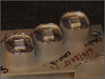
Perform a simulation of a Laser Powder Bed Fusion (L-PBF) additive manufacturing process of a thin-walled canonical part printed with Inconel 718 nickel chromium alloy.
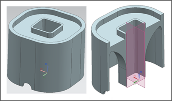
Find the distortion in the X direction along an edge of the part and compare results to measurements taken of the built part.
Analysis Assumptions and Modeling Notes
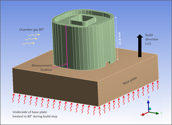
The simulation includes a build step and a cooldown step. Heat is applied at a constant temperature (80°C) to the underside of the base plate during the build step. Room-temperature convection is applied to that same surface during the cooldown step. Throughout the simulation the base plate is anchored by a fixed boundary condition on the underside of the plate. Ansys predefined material properties are used for Inconel 718 from the Additive Manufacturing Materials library. Deflection results from the vertical centerline of a side face are verified by comparing to experimental data. The analysis is performed using a Cartesian mesh.
| Build Settings | Build Conditions | Cooldown Conditions |
|---|---|---|
| Deposition/Powder Layer Thickness = 0.03 mm | Preheat Temperature = 80°C | Room Temperature = 22°C |
| Hatch Spacing = 0.1 mm | Gas Temperature = 80°C | Gas Temperature = 22°C |
| Scan Speed = 1000 mm/sec | Powder Temperature = 80°C | Powder Temperature = 22°C |
| Dwell Time = 10 sec | Gas Convection Coeff = 0.00001 W/mm2°C | Gas Convection Coeff = 0.00001 W/mm2°C |
| Dwell Time Multiple = 1 | Powder Convection Coeff = 0.00001 W/mm2°C | Powder Convection Coeff = 0.00001 W/mm2°C |
| Number of heat sources = 1 | Powder Property Factor = 0.01 | Powder Property factor = 0.01 |
| Mesh and Material Settings |
|---|
| Element size = 0.4 mm Cartesian mesh |
| Projection Factor = 0.5 |
Results Comparison
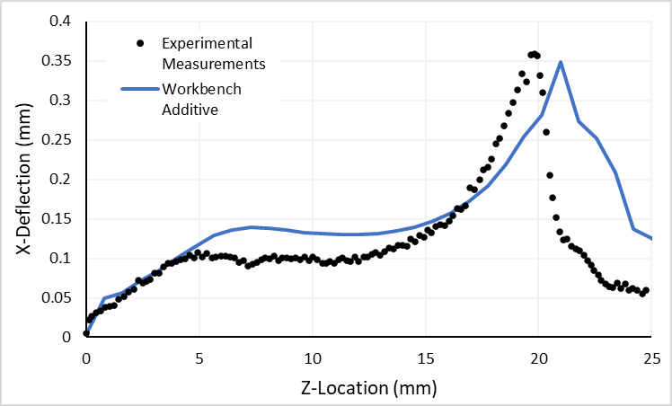
The distortion in the X direction as calculated by both solvers follows the trend of the measured results.
| Results | Target | Mechanical | Error (%) |
|---|---|---|---|
| X Deformation at Z = 4.83 mm | -0.11 | -0.11586 | 5.327 |
| X Deformation Maximum | -0.359 | -0.34817 | -3.017 |
Figure 185: Comparison of Predicted X Deflection Along Edge to Measured Data - Additive in Mechanical