


Display Element Normals on Mesh enables you to display a normal vector for each element. The normal vector orientation ensures the accurate representation and analysis of the Multiphysics effects within the cell structure. The default value is No. The available options are Yes and No. You can access Display Element Normals on Mesh from File > Options > Graphics > Default Graphics Options.
Hexahedral Element
For hexahedral element, you should pay attention to the connectivity, to ensure the correct orientation of the through-thickness direction. The mesher establish the orientation direction of hex elements considering the topological face selection as a reference point to determine the lower portion of the reoriented hex element. The shared internal faces are not considered for determining the orientation as the internal algorithm autonomously expands the hex layer for re-orientation, starting from the anchor face and progressing inwards.

Here,
nodes 0 to 3 define the lower surface.
nodes 4 to 7 define the upper surface.
face index 4 represents the bottom face.
face index 5 represents the top face.
The normal to face index 5 defines the normal of the hex element.
Wedge Element
For a wedge element, the connectivity of nodes defines the element’s orientation.
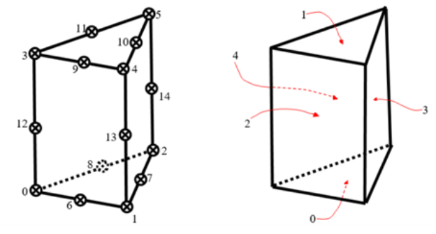
Here,
nodes 0 to 2 define the lower surface.
Nodes 3 to 5 define the upper surface.
face index 0 represents the bottom face.
face index 1 represents the top face.
The normal to face index 1 defines the normal of the wedge element.
Note: Hexahedral and wedge elements only support normal.