


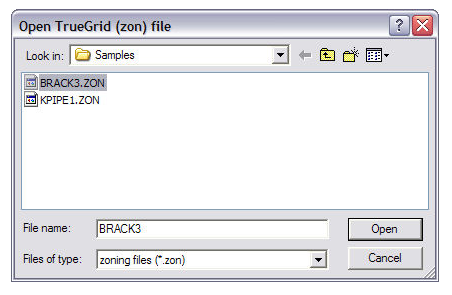
This window lets you import grid data from TrueGrid®.
Navigate to the TrueGrid®
zoning file you want to import (.zon) and click  to open the following window.
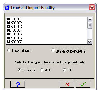
Blocks
The TrueGrid® zoning file contains one or more blocks of nodes (imported as Parts). These are displayed in the scrolling box at the top of the window.
If Import selected parts is checked, you can select one or more blocks.
- Import all Parts
Imports all the blocks as Parts.
- Import selected Parts
Imports selected blocks as Parts. Select the blocks you want to import in the top box.
- Select solver type
Select the solver type you want to assign to the imported Parts.
Click  to import the Parts.
Parts are imported with their block name. You can change these block names later in the Parts panel.
TrueGrid® zoning file format
There are two formats of TrueGrid® zoning files supported by Autodyn - implicit and explicit. The two formats are illustrated below by an example which generates a single cell cubic part (IMAX=2, JMAX=2, KMAX=2) called SUB1 with corners (0.0,0.0,0.0) and (1.0,1.0,1,0) and a four cell cuboid part (IMAX=2, JMAX=2, KMAX=3) called SUB2 with corners (2.0,2.0,2.0) and (3.0,3.0,4.0).
The implicit form of this data would be as follows:
IMPLICIT        Indicates implicit input is to follow
SUB1            Name of the part for which data follows
1 2 1 2 1 2     The (I,J,K) range for the data I=1, 2, J=1,2, K=1,2
0.0 0.0 0.0     (x,y,z) coordinates for node with index (1,1,1)
0.0 0.0 1.0     (x,y,z) coordinates for node with index (1,1,2)
0.0 1.0 0.0     (x,y,z) coordinates for node with index (1,2,1)
0.0 1.0 1.0     (x,y,z) coordinates for node with index (1,2,2)
1.0 0.0 0.0     (x,y,z) coordinates for node with index (2,1,1)
1.0 0.0 1.0     (x,y,z) coordinates for node with index (2,1,2)
1.0 1.0 0.0     (x,y,z) coordinates for node with index (2,2,1)
1.0 1.0 1.0     (x,y,z) coordinates for node with index (2,2,2)
SUB2            Name of the part for which data follows
1 2 1 2 1 3     The (I, J, K) range for the data I=J, 2, J=1,2, K=1,3
2.0 2.0 2.0     (x,y,z) coordinates for node with index (1,1,1)
2.0 2.0 3.0     (x,y,z) coordinates for node with index (1,1,2)
2.0 2.0 4.0     (x,y,z) coordinates for node with index (1,1,3)
2.0 3.0 3.0     (x,y,z) coordinates for node with index (1,2,1)
2.0 3.0 4.0     (x,y,z) coordinates for node with index (1.2,2)
3.0 2.0 2.0     (x,y,z) coordinates for node with index (2,1,1)
3.0 2.0 3.0     (x,y,z) coordinates for node with index (2,1,2)
3.0 2.0 4.0     (x,y,z) coordinates for node with index (2,1,3)
3.0 3.0 2.0     (x,y,z) coordinates for node with index (2,2,1)
3.0 3.0 3.0     (x,y,z) coordinates for node with index (2.2,2)
3.0 3.0 4.0     (x,y,z) coordinates for node with index (2,2,3)
END
The explicit form of this data would be as follows:
EXPLICIT              Indicates explicit input is to follow
SUB1                  Name of the part for which data follows
1 1 1 0.0 0.0 0.0     (x,y,z) coordinates for (1,1,1)
1 1 2 0.0 0.0 1.0     (x,y,z) coordinates for (1,1,2)
1 2 1 0.0 1.0 0.0     (x,y,z) coordinates for (1,2,1)
1 2 2 0.0 1.0 1.0     (x,y,z) coordinates for (1,2,2)
2 1 1 1.0 0.0 0.0     (x,y,z) coordinates for (2,1,1)
2 1 2 1.0 0.0 1.0     (x,y,z) coordinates for (2,1,2)
2 2 1 1.0 1.0 0.0     (x,y,z) coordinates for (2,2,1)
2 2 2 1.0 1.0 1.0     (x,y,z) coordinates for (2,2,2)
SUB2                  Name of the part for which data follows
1 1 1 2.0 2.0 2.0     (x,y,z) coordinates for (1,1,1)
1 1 2 2.0 2.0 3.0     (x,y,z) coordinates for (1,1,2)
1 1 3 2.0 2.0 4.0     (x,y,z) coordinates for (1,1,3)
1 2 1 2.0 3.0 2.0     (x,y,z) coordinates for (1,2,1)
1 2 2 2.0 3.0 3.0     (x,y,z) coordinates for (1.2,2)
1 2 3 2.0 3.0 4.0     (x,y,z) coordinates for (1,2,3)
2 1 1 3.0 2.0 2.0     (x,y,z) coordinates for (2.1,1)
2 1 2 3.0 2.0 3.0     (x,y,z) coordinates for (2,1,2)
2 1 3 3.0 2.0 4.0     (x,y,z) coordinates for (2,1,3)
2 2 1 3.0 3.0 2.0     (x,y,z) coordinates for (2,2,1)
2 2 2 3.0 3.0 3.0     (x,y,z) coordinates for (2.2,2)
2 2 3 3.0 3.0 4.0     (x,y,z) coordinates for (2,2,3)
STOP                  Indicates end of all data
With the explicit format, it is not necessary to define coordinates for a complete block of nodes in index space, and the order in which nodes are defined is unimportant.
When this option is used for a specific block of nodes in index space, the "indent.zon" file is scanned and only those nodes defined in this file and within the specified part and block to be initialized will be assigned coordinate values. Thus, standard zoning options could be used to define the bulk of the grid and the "User" option called to redefine the coordinates of a few isolated nodes.
Before reading in an explicit zoning file, the parts must already be created. The file can then be read in using the Import button on the Parts Zoning panel.
The above example is for 3D. For 2D models the format is the same except of course there is no K index or Z coordinates.