


This window lets you Define the zoning for your Shell Part.
Plane
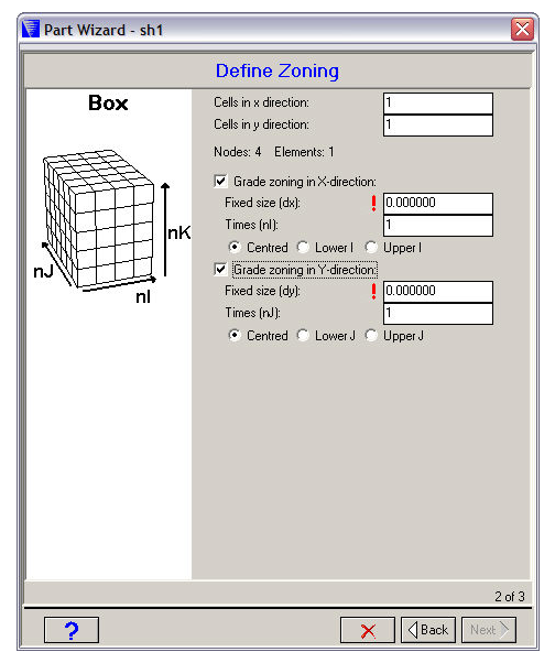
- Cells
The number of cells (elements) you want to use in the X, Y, Z directions. The corresponding number of nodes and elements required for your part will be displayed below.
- Grade zoning
Check the boxes if you want to grade your zoning in any direction.
If you choose this option you can specify a range of cells which have a fixed size. The remaining cells will be smoothly graded to fit the overall dimension of the box you specified in the previous window.
- Fixed size
The dimension you want to use for the fixed size cells.
- Times
The number of fixed size cells you want to use.
- Position
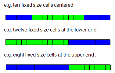
Specify where you want to place the fixed size cells relative to the full I/J/K range.
- Centered
At the center of the full I/J/K range.
- Lower
At the lower end of the I/J/K range.
- Upper
At the upper end of the I/J/K range.
Cylinder
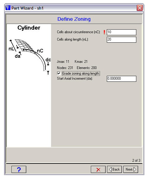
- Cells about circumference
The number of cells (elements) you want to use about the circumference of your cylinder.
- Cells along length
The number of cells (elements) you want to use along the length of your cylinder.
- Number of elements
Displayed below the above two input fields is the index space that will be used for your Part and the number of nodes and elements required.
- Grade zoning along length
Check this box if you want to grade the zoning along the length of your cylinder (you will be asked to specify a starting increment to use).