


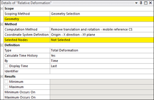
The following properties are available for the Relative Deformation object:
- Scoping Method
Scoping options include (default) and . Valid geometries include Bodies, Faces and Edges.
: used to define geometry selections. Appears when Scoping Method is set to .
: drop-down list of available Named Selections. Appears when Scoping Method is set to .
- Computation Method
Determines how transformations are handled in relation to a fixed or mobile reference coordinate system. The available methods are:
: This method removes translation only, while keeping the reference coordinate system fixed. It is useful when only the positional shift must be eliminated while maintaining the original orientation.
: This method removes both translation and rotation by aligning the coordinate system dynamically to reduce relative motion.
: This method removes rigid body motion from the total displacement field by applying a minimization approach. This ensures that only the relative deformation is considered, eliminating unwanted translational and rotational effects. A reference point is used to adjust the displacement field by subtracting its displacement from the overall result. The reference point is typically a node in the model and is determined as follows:
If the Coordinate System Definition is set to , the reference point is computed automatically from the center of gravity of the selection.
For other cases, the reference point is the first node selected using the Selected Nodes property.
- Coordinate System Definition
Defines how the coordinate system is established for transformation purposes. The available options are:
: The coordinate system is defined using an origin point, an X-direction vector defined from the first two nodes, and the plane containing the X and Y axes derived from the first and third selected nodes (see below).
: The coordinate system is derived from three specified nodes forming a circle. This method allows you to define an origin at a location that might not have a node, typically at the center of a circular or cylindrical area.
: Uses the predefined global coordinate system, but this option is only valid when the Computation Method is set to .
- Selected Node
This property allows you to define a custom, moving coordinate system by selecting three nodes in the graphical interface and applying them. This coordinate system is used to track relative deformation.
To define the coordinate system:
Select three nodes in the graphical view.
Click to confirm the selection.
The coordinate system is defined based on the chosen Coordinate System Definition option.
- Origin - X direction - XY plane
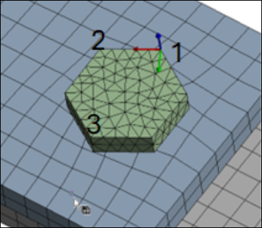
The first selected node is the origin.
The first and second nodes define the X-axis.
The first and third nodes define the XY-plane.
- Circle from 3 Nodes
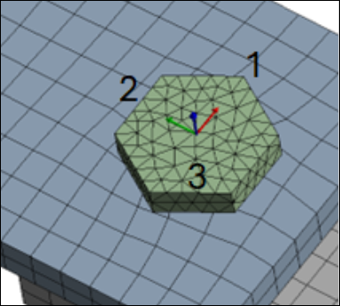
The three selected nodes define a circle.
The origin (O) is automatically placed at the center of the circle formed by the three nodes.
O and the first selected node define the X-axis.
O and the second node define the XY-plane.
- Definition Type
Options include and . When is selected, additional properties are exposed to select Orientation (X, Y or Z direction) and Coordinate System Type (Cartesian or Cylindrical).
- Calculate Time History
Specify whether to automatically calculate time history during the solution process. Options are (default) or .
- By
The options for this property enable you to specify how you wish to review result contours from multiple result sets.
The following options are available:
(default): This option displays the results for a particular time in the solution history. By default, this is the end time. For a solution that includes steps and substeps, you can use the Display Time property to specify a desired time value. If you specify a time that lies between two times that exist in the result file, the application interpolates the results.
: This option displays the contour result for a given result set contained in the result file. By default, this value is the last set. If only one set is available, then that is the specified result set. For a solution that includes load steps and substeps, you can specify the desired chronological set number using the Set Number property. You must enter a valid set number.
: Each node is swept through the result sets to find its maximum result. Either the result itself is reported or the time at which the peak occurred is reported.
: Each node is swept through the result sets to find its minimum result. Either the result itself is reported or the time at which the minimum occurred is reported.
- Results
Indicates the Minimum and Maximum relative deformation observed within the selected geometry. Also, the location of minimum and maximum values is indicated in the Minimum Occurs On and Maximum Occurs On property fields.