


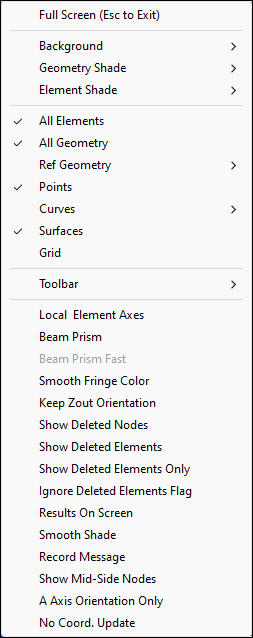
- Full Screen(Esc to Exit)
Show drawing area in full screen mode.
- Background
Set drawing area background (plain, fade, diaface, etc.).
- Geometry Shade
Set geometry displaying mode (Shaded geom with/no edges).
- Element Shade
Set element displaying mode (hidden, shaded, wireframe, feature line, etc.).
- All Element
Show/hide all elements.
- All Geometry
Show/hide all geometry.
- Ref Geometry
Show/hide reference geometry(ref axis, plane, point, coordinate system).
- Points
Show/hide geometry points.
- Curves
Show/hide geometry curves.
- Surfaces
Show/hide geometry surfaces.
- Grid
Show/hide grid in plane.
- Toolbar
Show/hide toolbar, show toolbar in text, icon or text and icon mode, and set font size.
- Local Element Axes
Toggle between global/local.
- Beam Prism
Toggle between line/prism.
- Beam Prism Fast
Speed up the graphics when displaying beam elements as prism objects.
- Smooth Fringe Color
Enable smoothing of contours (applicable only when in fringe mode).
- Keep Zout Orientation
Maintain orientation when zooming out.
- Show Deleted Nodes
Display deleted nodes when viewing LS_DYNA results.
- Show Deleted Elements
Display deleted elements when viewing LS_DYNA results.
- Show Deleted Elements Only
When running LS-DYNA, elements can fail or break and will be marked as "deleted element" in the d3plot file. Toggle this option to show only the elements that have been marked as deleted by LS-DYNA.
- Ignore Deleted Elements Flag
If an element is marked as deleted, the element is not shown by default - it will look as if it is not there. Toggle this option to ignore if an element has been marked as deleted and display it as if it was not deleted.
- Results On Screen
Display results on screen when Show Results is active in the Ident interface .
- Smooth Shade
Set shade mode as flat or smooth.
- Record Message
Write command message to lspost.msg file.
- Show Mid-Side Node
Display Mid-Side node in high order elements.
- A Axis Orientation Only
LS-PrePost can display element orientation for solid elements. This is done by drawing the main direction "A-axis" with an arrow and, to fully define an orientation, a "B-axis". In some instances, a clearer image can be viewed with the A axis only. Toggle this option to view the A axis orientation only.
- No Coord. Update
The coordinates of the nodes remain in their original location, regardless of which state is displayed. You will still be able to fringe plot results, but the geometry does not deform.