


Use this interface to create virtual strain gauge(VSG) element(s) and measure the engineering strain(s). The starting point(p1) and ending point(P2) of the VSG element can be on nodes or on the surface of the element, which makes it possible to correctly place the VSG element and measure the engineering strain according to the testing measurement. The engineering strain is calculated based on the node displacement of the elements where the VSG element intersects with.
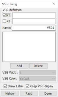
- P1
Pick the 1st point to define the virtual strain gauge.
- P2
Pick the 2nd point to define the virtual strain gauge.
- Name
User-defined name for virtual strain gauge.
- Add
Add current definition(P1->P2) to the virtual strain gauge list.
- Delete
Delete selected virtual strain gauge(s) from list.
- VSG Width
Set VSG width, for selected VSG(s) only.
- VSG Color
Set VSG color, for selected VSG(s) only.
- Show Label
Show VSG name and result on the screen.
- Keep VSG display
Keep VSG display after exiting this interface.
- History
History plot for selected virtual strain gauge(s).
- Padd
Add vsg data to current XY-Plot window.
- Done
Exit this dialog.