


You can generate geometry models directly from G-code for your simulations. This method offers more accurate views of print characteristics, like deposition volume and geometric feature details, compared to using nominal CAD designs. The Additive DED add-in in the Discovery™ application provides a convenient Path to Part functionality, where, with a few clicks, the G-code-based model is automatically attached and ready for simulation in the Mechanical application.
Path to Part Workflow
Be aware of the following requirements for using the Path to Part functionality:
In addition to Ansys Workbench and Mechanical, the Ansys Discovery application must be installed and available for use.
You must enable the Additive DED add-in in the Discovery application's settings (File Menu > Settings > Add-ins) and then close the application. This is a one-time only step; once the add-in is enabled, it will stay enabled for future Discovery sessions.
The recommended workflow begins in Ansys Workbench, proceeds to Discovery, and ends in the Mechanical application. Data transfer between applications is smooth and many tasks are automated. The workflow is summarized in the figure below and described in the following steps.
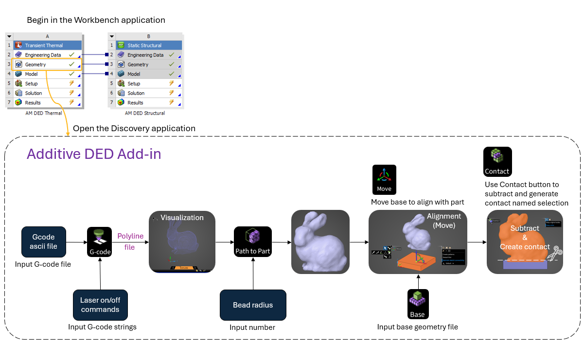
Set up an AM DED Process custom system in the Ansys Workbench application.
Double-click the Geometry cell to open the Discovery application.
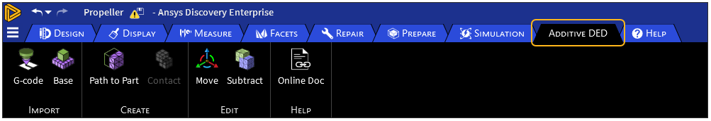
Click the Additive DED tab to view the add-on's custom ribbon.
Click Gcode and specify Laser On and Laser Off commands. Click the green checkmark in the heads-up display to import the G-code. Navigate to your G-code file and click Open.
The toolpath displays as purple lines. A Curves object is added to the tree. Also, a file called *_polyLines.txt is added to the folder in which the G-code file is located, where * is the name of your G-code file.
Click Path to Part and enter Bead Radius. Note: you can enter the radius in any unit system but when you click off the field, it always displays in meters. Select the Curves object in the tree and then click the green checkmark to complete the Path to Part conversion. You can select individual curves rather than all curves to specify different bead sizes for different regions of the part. Hint: View the message in the lower, left corner of the status bar for guidance.
The part is rendered and a Facets object is added to the tree.
Click Base, navigate to the base geometry file, and click Open to import the base.
In case the part and base are not aligned, click the Move tool to move the base into alignment with the part. Be sure to align in all directions, X, Y, and Z. Hint: Toggle the Show/Hide buttons on the Curves and Facets objects to see them individually, as desired.
The next step is to ensure a clean surface connection between the part and the base with no overlapping regions. The Contact button uses the base as a cutter, subtracts it from the part, and creates a named selection for the contact surface on the part that will be needed for the simulation in Mechanical.
Start the operation by selecting the base face(s) in contact with the part facet body. Once this selection is made, the Contact button is enabled. Click Contact. Next, in the graphics window, select the facets body. This selection performs the subtract action and also creates a named selection for contact.
To see the new named selection, click the Named Selection icon in the status bar to open the Named Selection panel. The new named selection, called ContactSurfaceNS, appears in the list. Click ContactSurfaceNS to see the orange highlighted surface(s) on the model. It may be helpful to hide the base body.
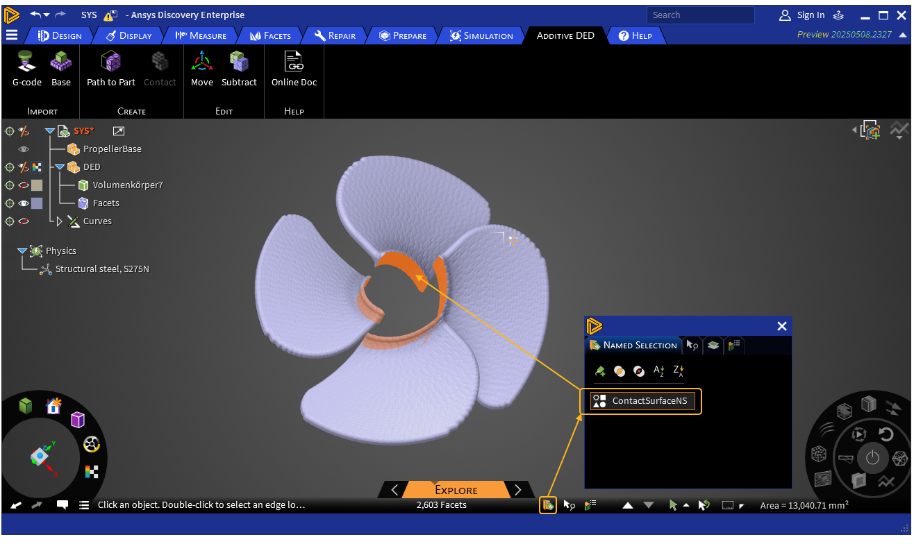
Limitation: If the Named Selection window is open before the Contact operation is performed, the named selection won't be displayed properly. Use Undo and Redo as needed to get back to the state before contact creation. Ensure the Named Selection window is closed before continuing.
At the end of the Contact operation, the part and base are automatically grouped together in the tree as a component called DED.
The Path to Part workflow is done at this point. Back in the Workbench application, double-click the Model cell to launch the Mechanical application. Continue your simulation using the DED Process Wizard as usual.
Tip: If you have a curved base, as shown in the propeller example above, Ansys recommends you set shared topology between the part and the base to force a better connection. You can do this in the Discovery application before you proceed to Workbench. In the tree, select the DED component. Click the Properties icon in the status bar to open the Properties panel. Click Transfer Sharing and then Share topology.