As engineers designing parts, we have long known that we need to adjust our CAD models to compensate for the anticipated distortion that occurs during manufacture. Distortion compensation capabilities in simulation software can be powerful tools to correct for these distortions. The process of creating a successful distortion-compensated geometry may be as simple as a single solve, or it may take multiple iterations of compensating and resolving to converge on the tolerance criteria. The determination of which approach to use depends on our application requirements. The Distortion Compensation Add-on in the Ansys Mechanical™ application provides two alternate approaches:
A single-run approach, in which a compensated geometry is created by reverse-distorting a single, static structural result set using a distortion compensation factor. This approach is very quick and may provide a satisfactory geometry in many cases.
An automated, iterative approach, in which simulations are run until a geometry is generated that, after manufacture, deforms to within tolerances of the original design. This approach usually involves longer overall run times than Single Compensation because of multiple iterations but results in an optimized geometry.
The following example demonstrates the iterative compensation technique used for distortion compensation.
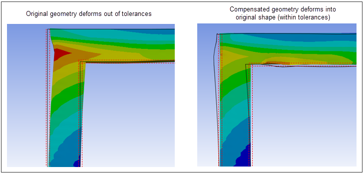
Left Image: Shows a geometry that has deformed beyond acceptable tolerances during the LPBF process. The gray outline indicates the initial geometry before simulation, while the red dashed lines mark the allowable tolerances.
Right Image: Displays the same geometry after undergoing automatic, iterative distortion compensation. The gray outline now represents the final, compensated geometry needed as the starting point to ensure the processed geometry remains within tolerances.