


Introduction
A lay-up can also include an Interface Layer for carrying out a fracture analysis of a composite solid model in the Mechanical application. The interface layer is a separation layer in the stacking sequence. It can be used to analyze the growth of existing cracks. The crack topology is defined with an interface layer in ACP while all other fracture settings are specified in Engineering Data (material models) or Mechanical application.
Note: Interface Layers are only taken into consideration in solid model generation and further processes. All shell-based analyses ignore any Interface Layers.
Mechanical APDL Solver
The interface layers are exported as INTER204 or INTER205 elements and can easily be used to set up a Cohesive Zone Model (CZM) or a Virtual Crack Closure Technique (VCCT) analysis. They can also be used to define contact zones between two layers. For more information, see Interface Delamination and Contact Debonding in the Mechanical User's Guide.
LS-DYNA Solver
Supported since Release 2025 R1.
Interface Layers are converted into zero volume LS-DYNAA cohesive elements (ELFORM=19) with a material model *MAT_COHESIVE_MIXED_MODE. In the Engineering Data, it is defined by material model Bilinear for Interface Delamination.
While contact debonding between plies is not supported yet, debonding between bodies is supported. The setup can be done directly in the Mechanical application (Interface Layer is not needed). Bonded contacts are converted into LS-DYNA tiebreak contacts with a fracture model based on *MAT_COHESIVE_MIXED_MODE. In the Engineering Data, the supported cohesive zone material model is Fracture-Energies based Debonding.
For more information, see LS-DYNA User's Guide.
LS-DYNA Solver Limitation: The Open Area feature of the ACP Interface Layers is not supported.
Definition
The Interface Layer is defined by two sets of surfaces:
The first set is the total surface of the open interface. This is the surface along which a crack can propagate. It is defined by an Oriented Selection Set in Interface Layer Properties dialog under the General tab.
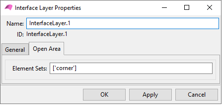
The second set is the surface of the open interface. It is defined by an Oriented Selection Set in Interface Layer Properties dialog under the Open Area tab.
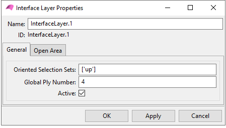
The Interface Layer can be activated or deactivated with a check box. You can also change the global number of an Interface Layer (Global Ply Number).